Solved

Off Axis Parabolic mirror collimation


swhobbs

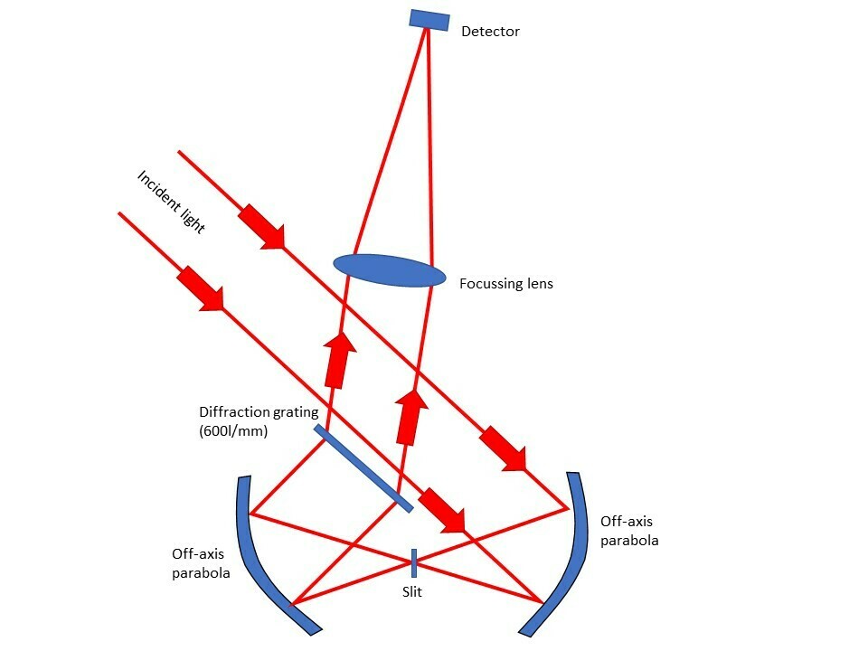
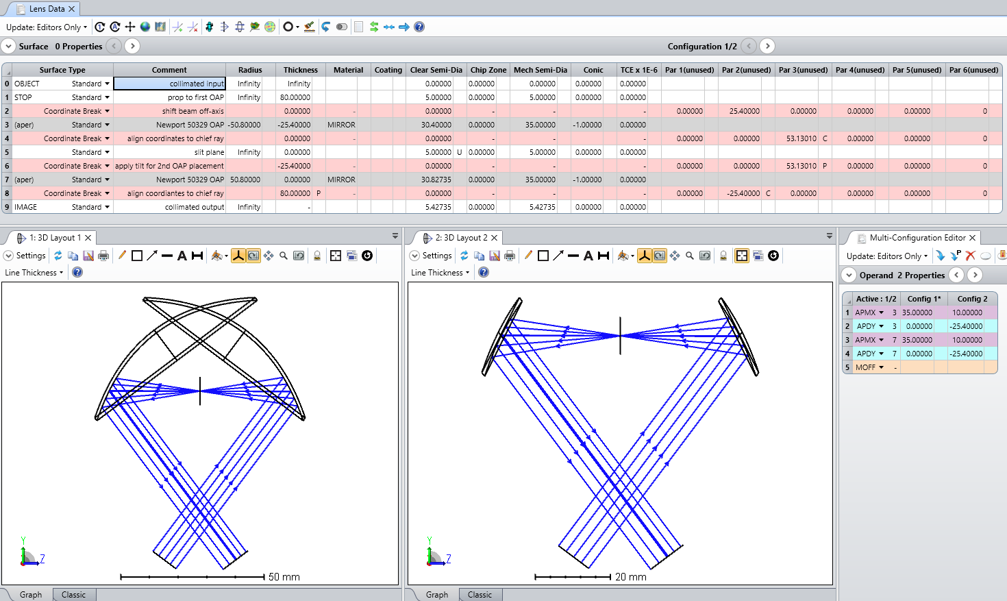
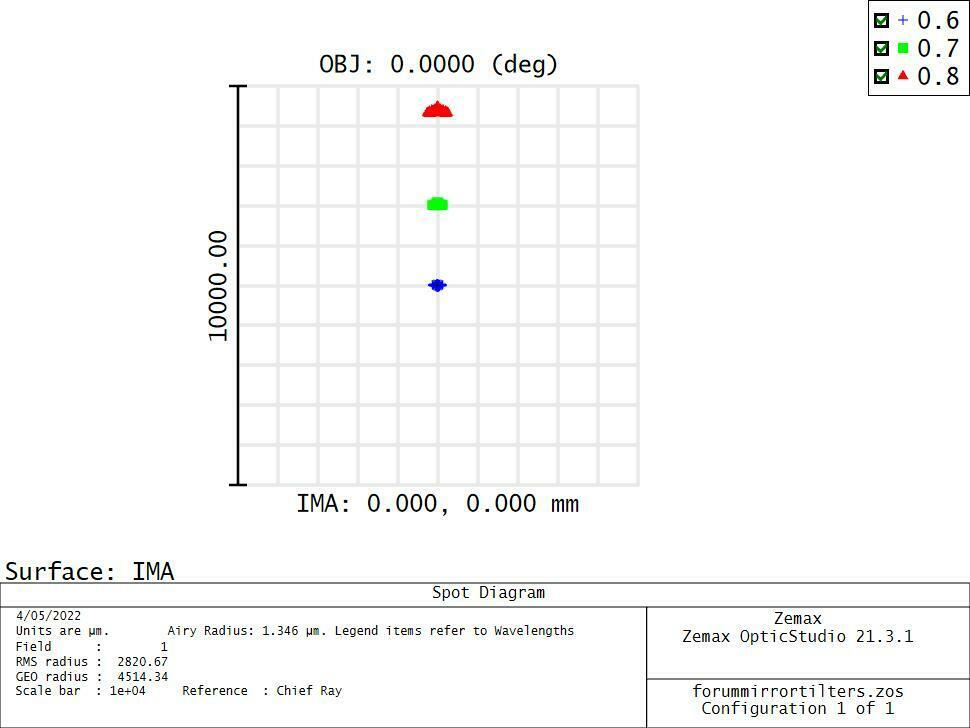
I am trying to customise the design by using two off axis parabolic mirrors (an objective, a collimator, and finally a focus lens). Slit and diffraction grating will follow; however I am unable to get 2 X parabolic mirrors to behave properly. I need to get incident light to reflect from the first mirror to the second, and then pass to focus through the lens. As can be seen something is very wrong. I have followed the two parabolic mirror tutorials on Zemax however find the trouble starts by trying to have two parabolic mirrors. Any help would be great - and sorry for the continued requests for help.


Best answer by Jeff.Wilde

Working with OAPs in sequential mode can be tricky.  Below is an example of what I think you are looking to accomplish.  Here are a few tips.  First, use the parabolic surfaces with their full apertures, then once things are aligned you can go back and add the off-axis apertures (in my example I’ve used two configurations, the first without the off-axis apertures and the second with them included).  Next, utilize chief-ray solves to help with nominal alignment of the on-axis field.  Once your system looks good, you can convert the solves to fixed values which locks the baseline design in place and allows for system perturbations to be investigated.  Lastly, it’s important to understand how the local coordinate system should change from surface-to-surface; in this regard it can be helpful to add display of the local coordinate systems as needed.


Hope this helps…

View original
Did this topic help you find an answer to your question?

4 replies

Jeff.Wilde
Luminary
Forum|alt.badge.img+3
  • Luminary
  • 490 replies
  • Answer
  • May 1, 2022

Working with OAPs in sequential mode can be tricky.  Below is an example of what I think you are looking to accomplish.  Here are a few tips.  First, use the parabolic surfaces with their full apertures, then once things are aligned you can go back and add the off-axis apertures (in my example I’ve used two configurations, the first without the off-axis apertures and the second with them included).  Next, utilize chief-ray solves to help with nominal alignment of the on-axis field.  Once your system looks good, you can convert the solves to fixed values which locks the baseline design in place and allows for system perturbations to be investigated.  Lastly, it’s important to understand how the local coordinate system should change from surface-to-surface; in this regard it can be helpful to add display of the local coordinate systems as needed.


Hope this helps…


swhobbs
  • Author
  • Monochrome
  • 7 replies
  • May 2, 2022

Wow this is a great design. I inputted it and got a much improved layout - then added a precision aspheric lens for a focus.

I had to stop the setup down to 10mm (I wanted 20mm) but the spot diagram is showing more distortion than I would have expected.

Have I missed a value somewhere?


Jeff.Wilde
Luminary
Forum|alt.badge.img+3
  • Luminary
  • 490 replies
  • May 2, 2022

The devil is in the detail!  Your lens parameters are wrong (no asphere coefficients are present, and in fact the last lens surface isn’t even designated as an asphere).  Simply load the lens model from the built-in Edmund Optics catalog and you will see much better results.  When errors arise, it’s important to first carefully check all the component parameters.


swhobbs
  • Author
  • Monochrome
  • 7 replies
  • May 5, 2022

Thank you so much for your response. I think I have fixed it now. I found the above performance with 15mm of aperture - it degrades rather severely with 20mm aperture - even after trying a non achromat past the grating. I had hoped the mirrors would have provided better optical performance?


Reply


Cookie policy

We use cookies to enhance and personalize your experience. If you accept you agree to our full cookie policy. Learn more about our cookies.

 
Cookie settings