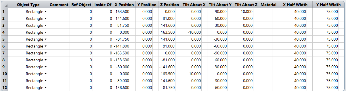
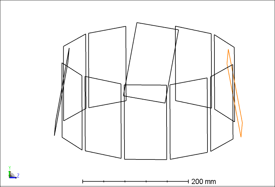
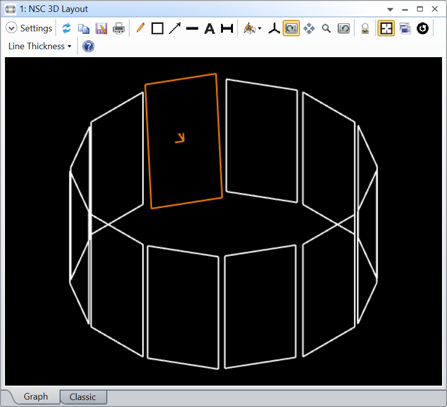
In non-sequential mode, I’ve created a circle of rectangles arranged around a light source (not shown). I’ve used the Paramter “Tilt About Y” to orient the rectangles’ faces toward the center. Now, I’m trying to tilt the rectangles 10° toward the central axis, but I’ve only been able to achieve this for objects #4 (highlighted) and #10. When I attempt to tilt the other rectangles forward, e.g. object #1 (centered in the screenshot), all I can accomplish is to rotate the rectangles clockwise or counterclockwise. Changing the values in “Tilt About X” and “Tilt About Z” seems to have the same effect. How can I make all the rectangles tilt towards the center, just like #4 and #10?
Best answer by David.Nguyen
@Daniel Stephan
The issue is that the Positions and Tilts are applied sequentially and in the order X Pos->Y Pos->Z Pos->X Tilt->Y Tilt->Z Tilt, if I’m not mistaken. If you only have a single tilt (X, Y, or Z), there is no issue. But in your case, your starting point is defined around a Tilt About Y. Then, you try to add a Tilt About X. The issue is that OpticStudio will first do the Tilt About X, which will also rotate the local axis of this object, and then perform the Tilt About Y.
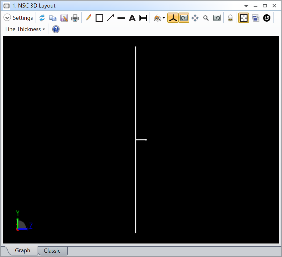
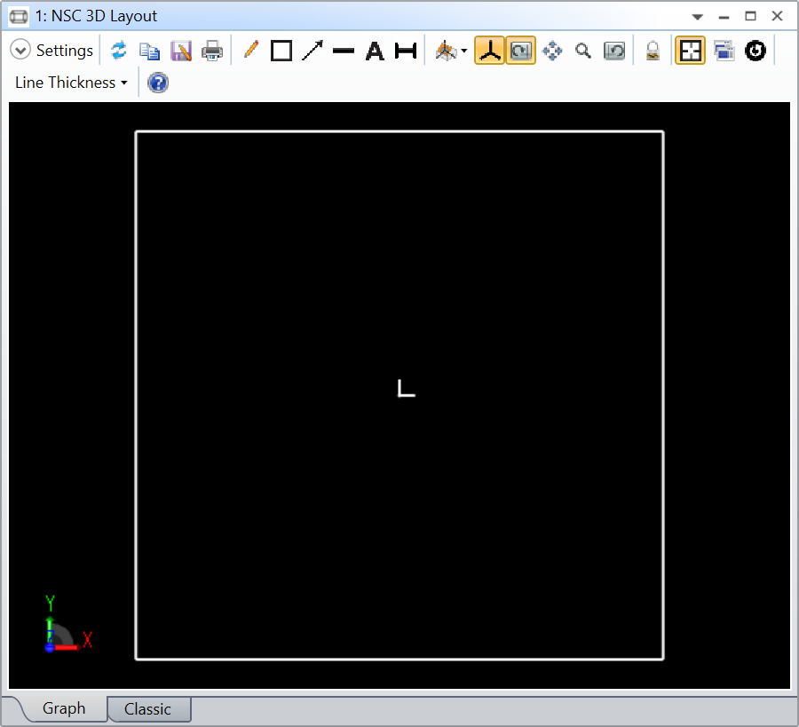
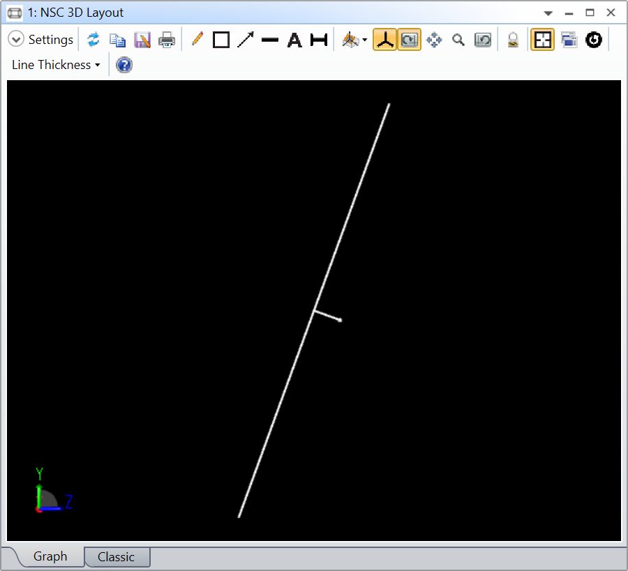
One thing that helps is to visualize the local axis of an object. This can be done in the Non-Sequential Component Editor (NCE), under the Object Properties..Draw..Draw Local Axis. If you do this with a single Rectangle, you get the screenshots below:
In the Y-Z view, there’s a long arrow pointing in the Global Z direction (horizontal towards the right-hand side of the screenshot).In the X-Y view, there are two axes (without arrowheads) aligned with the Global X and Y directions.
Now look at what happens with this rectangle when I apply a Tilt About X of 20 degrees.
Y-Z view with a 20 degree Tilt About X.
As you can see, the Rectangle is tilted, but so is its local axis. If you were to do a Tilt About Z, it will be done about the tilted local Z axis (not the Global one thatn you see with a blue arrow in the screenshot above).
I hope this makes sense, let me know otherwise.
But that doesn’t answer your question. So, how do you solve this issue?
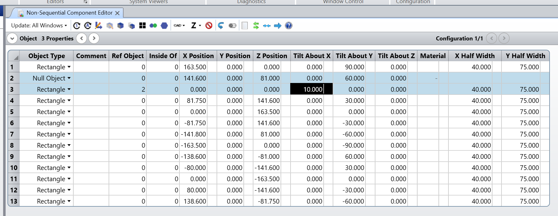
The trick is to use a dummy object (generally a Null Object) to define the starting position of your rectangles and use the Ref Object column to specify this dummy object as the reference location for your rectangle. And only apply the Tilt About X on the Rectangle object.
I manually copied your NCE (if you want to do the community a favor, please consider uploading a file next time), and made the change only for Rectangle 2 to show you. All the starting values are now in the Null Object just about Rectangle 3 (which was 2 before), and Rectangle 3 has 2 in the Ref Object column, and a Tilt About X only. That way, the Tilt About Y is done first through the Null Object, and then the Tilt About X is done on the Rectangle.
The reason your Rectangles 4 and 10 worked is because they have a Tilt About Y of 0 degree. Therefore, there is only a single tilt (About X) and the issue isn’t there anymore.
The issue is that the Positions and Tilts are applied sequentially and in the order X Pos->Y Pos->Z Pos->X Tilt->Y Tilt->Z Tilt, if I’m not mistaken. If you only have a single tilt (X, Y, or Z), there is no issue. But in your case, your starting point is defined around a Tilt About Y. Then, you try to add a Tilt About X. The issue is that OpticStudio will first do the Tilt About X, which will also rotate the local axis of this object, and then perform the Tilt About Y.
One thing that helps is to visualize the local axis of an object. This can be done in the Non-Sequential Component Editor (NCE), under the Object Properties..Draw..Draw Local Axis. If you do this with a single Rectangle, you get the screenshots below:
In the Y-Z view, there’s a long arrow pointing in the Global Z direction (horizontal towards the right-hand side of the screenshot).In the X-Y view, there are two axes (without arrowheads) aligned with the Global X and Y directions.
Now look at what happens with this rectangle when I apply a Tilt About X of 20 degrees.
Y-Z view with a 20 degree Tilt About X.
As you can see, the Rectangle is tilted, but so is its local axis. If you were to do a Tilt About Z, it will be done about the tilted local Z axis (not the Global one thatn you see with a blue arrow in the screenshot above).
I hope this makes sense, let me know otherwise.
But that doesn’t answer your question. So, how do you solve this issue?
The trick is to use a dummy object (generally a Null Object) to define the starting position of your rectangles and use the Ref Object column to specify this dummy object as the reference location for your rectangle. And only apply the Tilt About X on the Rectangle object.
I manually copied your NCE (if you want to do the community a favor, please consider uploading a file next time), and made the change only for Rectangle 2 to show you. All the starting values are now in the Null Object just about Rectangle 3 (which was 2 before), and Rectangle 3 has 2 in the Ref Object column, and a Tilt About X only. That way, the Tilt About Y is done first through the Null Object, and then the Tilt About X is done on the Rectangle.
The reason your Rectangles 4 and 10 worked is because they have a Tilt About Y of 0 degree. Therefore, there is only a single tilt (About X) and the issue isn’t there anymore.
@David.Nguyen Thank you so much for the detailed answer. I understand the problem now, and your solution using Null Objects as references works like a charm 👍