


Released: September 15th, 2020
1 Tools, Features, and Capabilities
1.1 Compound Lens Support
Use all the OpticsBuilder functionality with compound lenses
OpticsBuilder 20.3 now offers the ability to Convert & Build compound lenses. This new ability to convert and build compound lenses offers users more options when bringing mirrors into CAD. OpticsBuilder also supports the use of all features when working with an optical design containing compound lenses. Additional work was done to ensure reference geometry displays properly on these types along with the ability to add mounting edges correctly to compound lens object types. Compound lens support includes those made using standard, even/odd aspheric, and biconic surfaces.
1.2 Ability to Edit the Optical Design
Modify the optical design directly in your native CAD platform
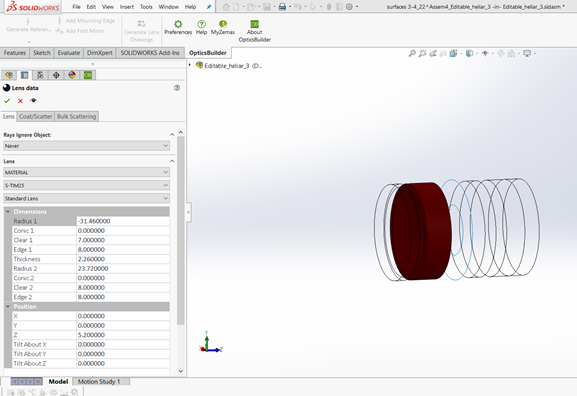
Using Prepare for OpticsBuilder in OpticStudio, optical engineers may untick a read only box to send a file to the OpticsBuilder user that will load with editing capabilities. This empowers the CAD user to be able to make changes as needed during their design cycle for packaging needs and constraints. CAD users are able to move and reposition the optical components, change their nonsequential optical properties, and edit their shape using the tools available in their CAD platform. This functionality is available on both the SOLIDWORKS and the Creo CAD platforms. The new nonsequential editing window is shown in SOLIDWORKS in Figure 1.2.a.
1.3 Section View With Partial Rays
Users may use section views to visualize rays inside of their design
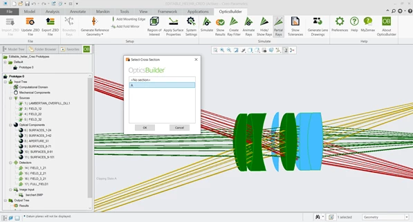
Users have an even more accurate inside look into their optical product designs. When applying a section view to their design in CAD, OpticsBuilder offers the ability to also apply the section view to the simulated ray set. In SOLIDWORKS, the section view is automatically applied when a section view is selected. In Creo, users must first create their section view and then select the new “Partial Rays” button to apply the section view to their rays. A demonstration of an activated section view of the rays in Creo is shown in Figure 1.3.a.
2 Usability
2.1 Rays Ignore Object
Improved ray tracing capabilities to give the same view as OpticStudio
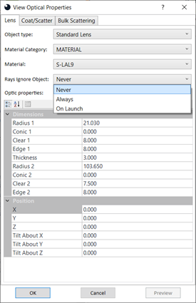
OpticsBuilder is now leveraging the functionality found in OpticStudio “Rays Ignore Object”. This setting is found in the “Optical Properties” of the optical components. This setting will mimic however it was set in the original OpticStudio design. Users may change this if the .ZBD was sent to them as non-read only. Rays Ignore Object has three options: never, always, and on launch. Please see the OpticsBuilder help document for more on this newly added setting. The new Rays Ignore Object selection is shown in Figure 2.1.a.
2.2 Nested Objects
Improved support for nested objects allows rays to trace as they would in OpticStudio
Prior to 20.3, if users loaded a file that includes an optical object placed inside of another, the ray trace would ignore the nested object and only take the outside object into consideration. With 20.3 we introduce functionality to the ray trace that includes both the nested and outside objects, giving users results that are closer to what they would get in OpticStudio.
3 Performance and Stability Improvements
OpticsBuilder 20.3 includes the following improvements:
- Optics Manager dividing line automatically stretches to prototype height
- Testing on new CAD libraries for adoption in OpticStudio and future speed improvements to OpticsBuilder.
- A warning message will pop-up if attempting to load a .ZBD file that was prepared for a different CAD platform.
- Lightweight mode in SOLIDWORKS- OpticsBuilder will force users to resolve items out of lightweight mode in order to run a Simulation. Lightweight mode does not give full data for an accurate simulation to be performed.
4 Bug Fixes
OpticsBuilder for SOLIDWORKS 20.3 includes the following bug fixes:
- Ability to re-run a ray trace after deleting rays– If a user deleted their simulated rays from the Optics Manager, OpticsBuilder would not allow them to re-run a Simulation. Users may now re-run Simulations after deleting rays from their Optics manager menu.
- Exported PMP data would round to the nearest integer– When creating an output file, the PMP data would round to the nearest integer. This data now remains as is, without rounding, when creating an output file.
- New parts added to the assembly had a mirror surface applied – When creating new CAD parts that are added to your optical product, they should default to have a black anodized surface, not a mirrored surface because mirrored surfaces are going to present the worst case scenario. We assign black anodized as a default to new CAD parts to ensure an accurate production representation.
OpticsBuilder for Creo 20.3 includes the following bug fixes.
- Creo 4 was not exporting all needed mechanical parts – OpticsBuilder for Creo 4 was not exporting some of the mechanical components when creating a .ZBD file export. OpticsBuilder for Creo 4 now exports all parts in the file.
- Creo crashes – We experienced a few scenarios where crashes would occur when using OpticsBuilder for Creo. These crashes needed exact settings to occur and have been fixed.
- Missing scatter profile in ScatterData folder causes mirrored surfaces without warning – If a scatter profile was applied to a surface in the .ZBD file and that scatter profile was not present in the ScatterData folder, OpticsBuilder would automatically apply a mirrored scatter profile to the surface without warning to the user. Mirrored scatter profiles show the worst-case scenario so they would yield a lot of errors in the Results window, further confusing users. An error message now displays warning the user that the scatter profile is missing and advising them to take steps to resolve the issue.