The Ray Database Viewer reports quite a bit of data, but it doesn't seem to have angle of incidence. Is there an option to show that information? Or do I have to derive it myself?

Solved
Is an angle of incidence report available in the Ray Database Viewer?

 +2
+2Best answer by Allie
OpticStudio 19.4 provides a lot of useful information in a Ray Database Viewer. All of this information is considered to be the “base” information and there is some useful information that a user might have to derive from this base information. The information reported is:
- Segment identification and history (left 6 columns)
- Interaction at a given surface (XRTSDGEFBZ columns)
- XYZ ray intercept coordinates
- LMN direction cosines
- Nx/Ny/Nz surface normal at the ray intercept
- Real & Imaginary E-field
- Path & Phase information
To visualize the LMN and Normals in terms of Angle of Incidence rather than the provided vector representation, you will need to derive the values yourself. To do so, you will need to use the equation for the angle between 2 vectors:

Translating this to OpticStudio values, you get the angle to be:

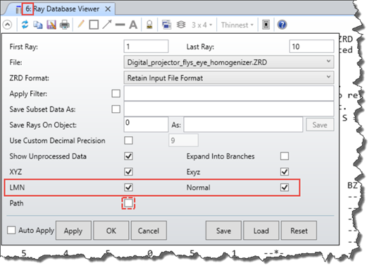
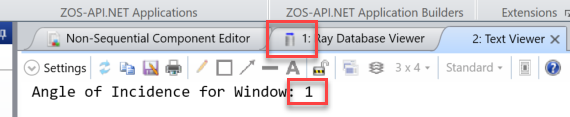
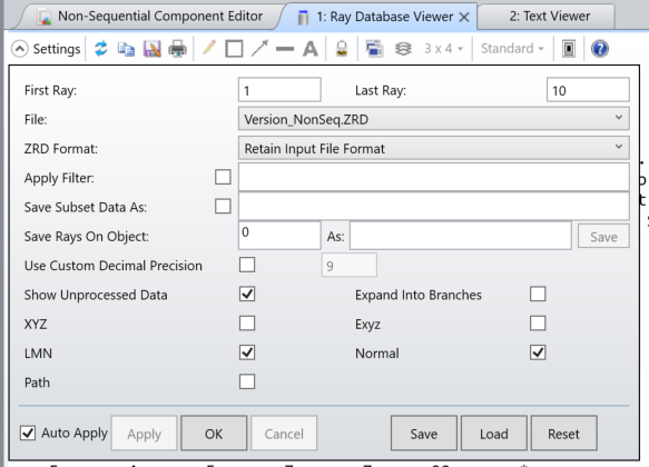
In order to automate this process, you can create a ZPL macro that will loop through each row in an opened Ray Database Viewer (the RDV needs to be opened to ensure that the proper LMN and Normal values are displayed since these can be toggled on & off). The ZPL attached in the next post will ask the user for the window number of the RDV, which is the number in the left part of the tab. The only 2 caveats for using this macro are:
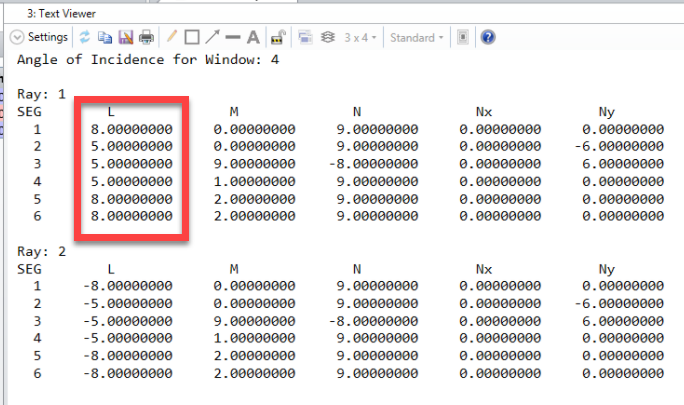
- Both the LMN and Normal boxes must be checked
- Only 4 out of the bottom 5 boxes can be checked
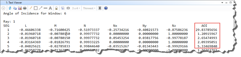
The following will be the output. Notice that the LMN and Normal components are printed out so you can verify that the inputs are correct. The last column will be the AOI of the ray with respect to the surface normal.


Reply
Enter your E-mail address. We'll send you an e-mail with instructions to reset your password.
Need more help?
To Chinese users:
Do not provide any information or data that is restricted by applicable law, including by the People’s Republic of China’s Cybersecurity and Data Security Laws ( e.g., Important Data, National Core Data, etc.).
不要提供任何受适用法律,包括中华人民共和国的网络安全和数据安全法限制的信息或数据(如重要数据、国家核心数据等)。