
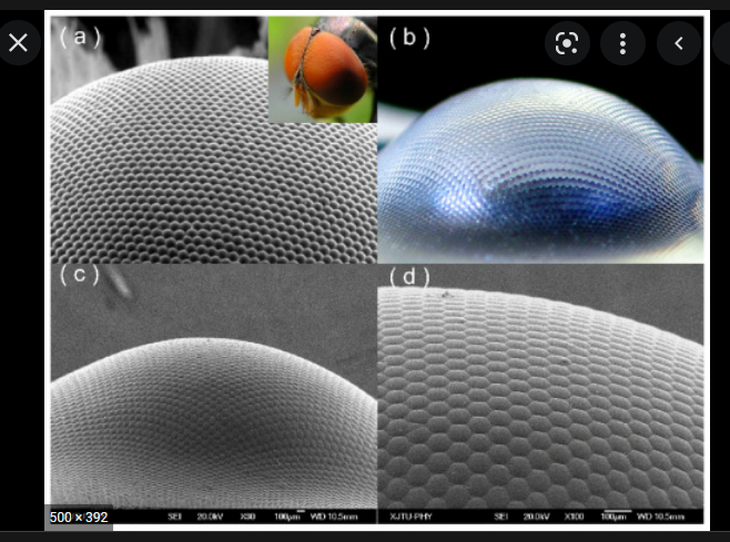
Is there any way to model a lensarry onto a spherical surface?
Example see below

Is there any way to model a lensarry onto a spherical surface?
Example see below
Best answer by David.Nguyen
Hi Sepp,
Strictly speaking, if you have a mathematical expression for how the lenslets are distributed on the spherical surface, which isn’t obvious at all, you could use the ZOS-API or a macro to create the lenslets and position them accordingly. You could use spherical coordinates to locate the lenslet, but the question becomes: how to pick the sampling rate?
I made a simple dummy example:
import numpy as np


# Number of samples for theta and phi
samp_t = 6
samp_p = 15

# Samples of theta and phi (using the physics convention: ISO 80000-2:2019 from Wikipedia on Spherical Coordinate System)
theta_space = np.linspace(0, np.pi/8, samp_t)
phi_space = np.linspace(0, 2*np.pi, samp_p, endpoint=False)

# Spherical surface radius
major_radius = 5.0

# Standard lens type (used later in the loop)
std_lens_type = TheSystem.NCE.GetObjectAt(1).GetObjectTypeSettings(ZOSAPI.Editors.NCE.ObjectType.StandardLens)

# Default direction cosine for new objects stored as Vector A (used later in the loop)
a_vec = np.array([0.0, 0.0, 1.0])

# Loop over theta and phi
for theta in theta_space:
    for phi in phi_space:
        # Calculate lenslet coordinates XYZ
        x_pos = major_radius * np.cos(phi) * np.sin(theta)
        y_pos = major_radius * np.sin(phi) * np.sin(theta)
        z_pos = major_radius * np.cos(theta)

        # Create new object (lenslet)
        lenslet = TheSystem.NCE.InsertNewObjectAt(1)

        # Change new object type to Standard Lens
        lenslet.ChangeType(std_lens_type)

        # Update new object XYZ position
        lenslet.XPosition = x_pos
        lenslet.YPosition = y_pos
        lenslet.ZPosition = z_pos

        # Update lenslet radius
        lenslet.GetObjectCell(ZOSAPI.Editors.NCE.ObjectColumn.Par6).DoubleValue = -2.0

        # There should only be a single lens at theta = 0.0 degree and it doesn't need a change of orientation
        if theta == 0.0:
            break

        # Calculate direction cosine of the normal to the spherical surface at the XYZ coordinates
        l_cos = x_pos / major_radius
        m_cos = y_pos / major_radius
        n_cos = z_pos / major_radius
        norm = ( l_cos**2 + m_cos**2 + n_cos**2 )**0.5
        l_cos /= norm
        m_cos /= norm
        n_cos /= norm

        # The normal direction cosine is stored as Vector B
        b_vec = np.array([l_cos, m_cos, n_cos])

        # Using this thread: https://math.stackexchange.com/questions/180418/calculate-rotation-matrix-to-align-vector-a-to-vector-b-in-3d
        # One can find the rotation matrix that aligns Vector A to Vector B
        v_vec = np.cross(a_vec, b_vec)
        c_val = np.dot(a_vec, b_vec)
        v_x = np.array([[0.0, -v_vec[2], v_vec[1]], [v_vec[2], 0.0, -v_vec[0]], [-v_vec[1], v_vec[0], 0.0]])

        # This is the rotation matrix
        r_mat = np.identity(3) + v_x + np.dot(v_x, v_x) / ( 1 + c_val )

        # Using this method: http://eecs.qmul.ac.uk/~gslabaugh/publications/euler.pdf
        # One can decompose the rotation matrix into three rotations along the cardinal axes
        # In our case, it is a little bit easier because the rotation about Z is the identity
        # matrix (the lenslets are rotationally symmetric in this simple example).
        # There is still an ambiguity (the rotation angle is an arccos of a matrix coefficient,
        # therefore there is the plus and minus solutions that are valid), which is solved by
        # looking at the lens XYZ coordinates
        if x_pos < 0:
            tay = -np.arccos( r_mat[0, 0] ) / np.pi * 180
        else:
            tay = np.arccos( r_mat[0, 0] ) / np.pi * 180

        if y_pos > 0:
            tax = -np.arccos( r_mat[1, 1] ) / np.pi * 180
        else:
            tax = np.arccos( r_mat[1, 1] ) / np.pi * 180

        # Update the lenslet orientation
        lenslet.TiltAboutX = tax
        lenslet.TiltAboutY = tay
Which gives the following result:
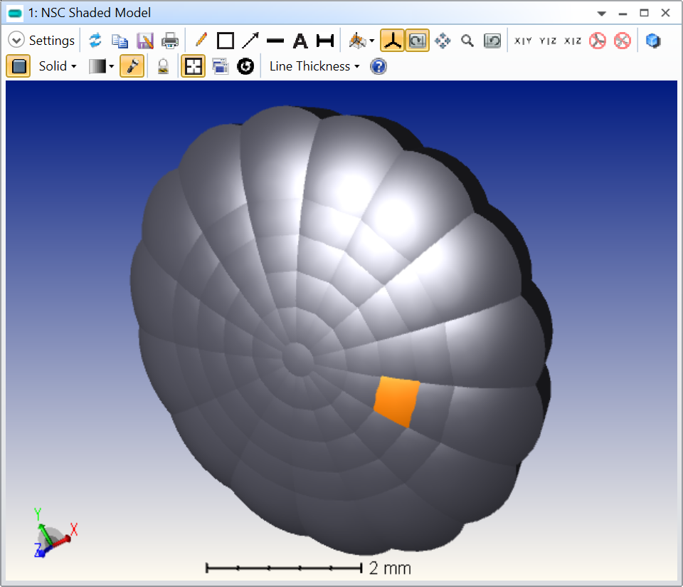
As you can see, using a uniform sampling leads to lenslet of different sizes and I don’t know how to solve that issue for your specific problem.
Alternatively, this array can probably be generated in a CAD software, and OpticStudio is able to import most of the CAD file formats.
Lastly, it might be worth clarifying what you are trying to achieve with this model. Can you consider a single lenslet at first? Are you interested in diffraction effects from the array?
Take care,
David
Enter your E-mail address. We'll send you an e-mail with instructions to reset your password.
Do not provide any information or data that is restricted by applicable law, including by the People’s Republic of China’s Cybersecurity and Data Security Laws ( e.g., Important Data, National Core Data, etc.).
不要提供任何受适用法律,包括中华人民共和国的网络安全和数据安全法限制的信息或数据(如重要数据、国家核心数据等)。
