Please, can anybody help with simulating different roughness surface finish expressed in VDI / Ra?
There is some plate made of Polycarbonate and has transmittance of 90%. I need to evaluate scattering of light depending on different roughness surface finish of one of the object faces. The factory can provide only VDI data. How can scattering be modeled knowing only VDI values?
Thanks

Solved
Scattering analysis of transparent objects with VDI roughness surface finish
Best answer by Olivier.Ripoll
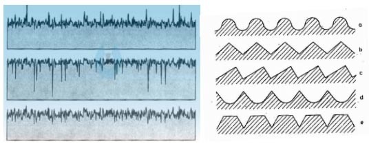
A roughness number does not tell what the shape of your surface structures is, and as a consequence, what the scattering is going to be. It only work in the other direction. You can have totally different surfaces with the same Ra (or Rq, or Sa, or Sq, ...).
See an illustrations on these pages
https://www.comcoinc.com/surface-finish-specs/basic-cmyk-3/
https://www.researchgate.net/publication/310861650_Optical_Characterization_of_Nanostructured_Surfaces/figures?lo=1
https://www.cnccookbook.com/surface-finish-chart-symbols-measure-calculators/
And this is for a 1D example. You may have a circular pattern, a linear pattern, or whatever anisotropic pattern so it is even more disconnected.
In addition, most of the time, people will give a single number while Ra (and friends) are functions of the spatial frequency of the structure (computed after applying 2-3 filters).
What such parameter can be used to is to define an acceptable limit for a given machine & process: You generate many samples and measure their roughness and their scattering, then determine what scattering is acceptable and you can set a limit to the roughness. As long as the same machine is used (e.g. SPDT generating a circular roughness pattern), that criterion is quite fine to set the acceptance.
Of course, if your Ra is 0, the surface is smooth and you have no scattering. That is the only case where you can know the scattering from the roughness: optically polished surfaces. In such cases Rq and Rdq (not Ra) can be useful (There used to be an article on Zemax knowledge base on the topic). But VDI data, from what I can see, is not for polished profiles (at best 100nm Ra).
View originalSee an illustrations on these pages
https://www.comcoinc.com/surface-finish-specs/basic-cmyk-3/
https://www.researchgate.net/publication/310861650_Optical_Characterization_of_Nanostructured_Surfaces/figures?lo=1
https://www.cnccookbook.com/surface-finish-chart-symbols-measure-calculators/
And this is for a 1D example. You may have a circular pattern, a linear pattern, or whatever anisotropic pattern so it is even more disconnected.
In addition, most of the time, people will give a single number while Ra (and friends) are functions of the spatial frequency of the structure (computed after applying 2-3 filters).
What such parameter can be used to is to define an acceptable limit for a given machine & process: You generate many samples and measure their roughness and their scattering, then determine what scattering is acceptable and you can set a limit to the roughness. As long as the same machine is used (e.g. SPDT generating a circular roughness pattern), that criterion is quite fine to set the acceptance.
Of course, if your Ra is 0, the surface is smooth and you have no scattering. That is the only case where you can know the scattering from the roughness: optically polished surfaces. In such cases Rq and Rdq (not Ra) can be useful (There used to be an article on Zemax knowledge base on the topic). But VDI data, from what I can see, is not for polished profiles (at best 100nm Ra).

Reply
Enter your E-mail address. We'll send you an e-mail with instructions to reset your password.
Need more help?
To Chinese users:
Do not provide any information or data that is restricted by applicable law, including by the People’s Republic of China’s Cybersecurity and Data Security Laws ( e.g., Important Data, National Core Data, etc.).
不要提供任何受适用法律,包括中华人民共和国的网络安全和数据安全法限制的信息或数据(如重要数据、国家核心数据等)。