In STAR, the Component RBM tool allows us to extract RBMs for a lens or mirror and automatically convert them to coordinate breaks.  Considering the FEA data on all surfaces in the optic, we calculate any RBMs that are common to the surfaces, to find the motion of the optic as a whole.  The component-level RBMs are reported, and a button converts the common RBMs into Coordinate Breaks.

Currently, this is a one-way transformation, so users are prompted to save their original file before converting to Coordinate Breaks.

(Extracting RBMs can be carried out for each surface individually, as well, to accommodate mirrors.  We could declare each surface of this lens as a separate component, and extract the RBMs for the front and back surface’s deformation data separately.  Note that currently, nesting of RBMs is not officially allowed, though there are some clever workarounds possible.)
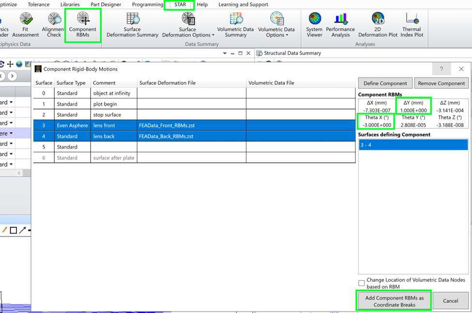
The Component Rigid-Body Motion tool in STAR allows users to automatically calculate RBMs that are common to the whole optic, and convert them to Coordinate Breaks in the model.

After removing the RBMs common to all surfaces that make up a component, any remaining RBMs on the individual surface are included in the new FEA data set.  In the Structural Data Summary, the residual surface RBMs are now shown in the RBM property of the surface.  The file names have also been altered to show that component-level RBMs are no longer included in the data.

Note that the “Extracted RBMs” column has been turned off!  Since the component-level RBMs are now captured as coordinate breaks, the Extracted RBMs column must be turned off to avoid doubling the RBMs.   
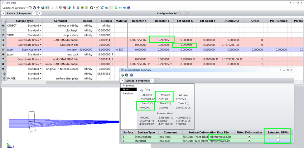
The system after converting the lens RBMs to Coordinate Breaks.

https://community.zemax.com/star-module-user-group-85/rigid-body-motions-rbms-in-star-part-1-overview-5392

https://community.zemax.com/star-module-user-group-85/rigid-body-motions-rbms-in-star-part-2-a-simple-singlet-5393

https://community.zemax.com/star-module-user-group-85/rigid-body-motions-rbms-in-star-part-3-evaluate-performance-with-and-without-rbms-5395

https://community.zemax.com/star-module-user-group-85/rigid-body-motions-rbms-in-star-part-4-a-note-about-apertures-and-rbms-5396

https://community.zemax.com/star-module-user-group-85/rigid-body-motions-rbms-in-star-part-5-converting-rbms-to-coordinate-breaks-5397

https://community.zemax.com/star-module-user-group-85/rigid-body-motions-rbms-in-star-part-6-converting-the-new-optic-positions-to-nonsequential-mode-5399

https://community.zemax.com/star-module-user-group-85/reminder-use-the-multiphysics-data-loader-to-remove-fea-data-from-a-system-5398

This is an excellent capability Erin. You and the team should get an award from SPIE/Optica for this. It’s a major step forward from the prior art in this area. - Mark


It really is.  One of the customers who was heavily involved in the development had his graduate students doing this translation to coordinate breaks by hand.  We did it for them.  😆  

Seriously, though, the ability to automatically put the RBMs in Coordinate Breaks is ridiculously useful.  Users can exercise the tilt & decenter values to quickly explore performance in the presence of better or worse temperature changes, among other things.  I would always ask for FEA data at two temperatures, so I can assume linear relationships and take a guess at system performance versus temperature.  And plan things like the focus adjust needed in the best-case scenario versus worst-case scenario.  And where to put the focal plane at room temperature so that it is centered on-orbit, best case and worst case.  This is super-powerful stuff.


Erin,

Great work this write-up series has been very helpful.  I had a question about the calculated RBM’s…

When observing the RBMs in the Structural Data Summary, which coordinate reference are they provided in?  The global or local coordinate reference based on the component?  

I have a non-axial symmetric system with coordinate breaks, so I’m wondering if I need to do coordinate transformations if I want RBMs in reference to the global coordinate reference.  (I hope not!)

-Jeff 


Hi, Jeff.  Thanks!  I’m always glad to hear that our content is useful.

I’m pretty sure that all RBMs are reported in local surface coordinates.  We always work in local, behind the scenes.

That said, I wonder if there’s a fairly simple workaround.  The problem is that you probably have allowed motions of the part in global coordinates, right?  So…. use CBs to move a dummy to your global coordinates, and set that as the Global Coordinate Reference Surface in the System Explorer / Aperture. 

If you just need to retrieve the global part position, you can move the part locally and retrieve the global coordinates using Analysis/Reports/Prescription Data / Global Coordinates, or using GLCX|Y|Z|A|B|C in the Merit Function Editor.

If you have allowed motions for the parts in global coordinates, then you don’t know the values that are needed in the local Coordinate Breaks.  But you could optimize to find those.  If you put the desired position change into the Merit Function Editor using GLCX|Y|Z|A|B|C, and set the local coordinate break X|Y|Z|A|B|C values to be variables, you can optimize to figure out the local coordinate values that you need.  You might run into some trouble handling the Z coordinate in the thickness column with this technique.(?)  And make sure that the pickups and order flag are all set properly in your local Coordinate Break pair before you start, so that the local motion of the part is always undone correctly.


Reply