New part positions due to the STOP effects can be captured in nonsequential mode of Zemax, too.
If the user has a sequential model with deformation data, the RBMs can be converted into Coordinate Breaks, and then the system can be converted to nonsequential mode. The new part positions due to the RBMs will translate correctly into nonsequential mode. (The higher-order deformations on the optic surfaces will not be converted and will be lost!)
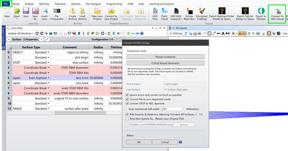
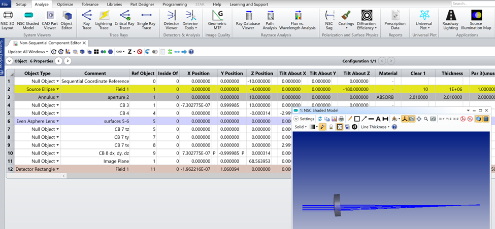
The example below shows this process for the singlet introduced in the previous articles. I’ve converted the RBMs that are common to the front and back surfaces of the lens into Coordinate Breaks. Then, I use the Convert to NSC Group button to create a Nonsequential model of the singlet that includes the new optic position of dY = 1 mm and Tilt about X = 3°.
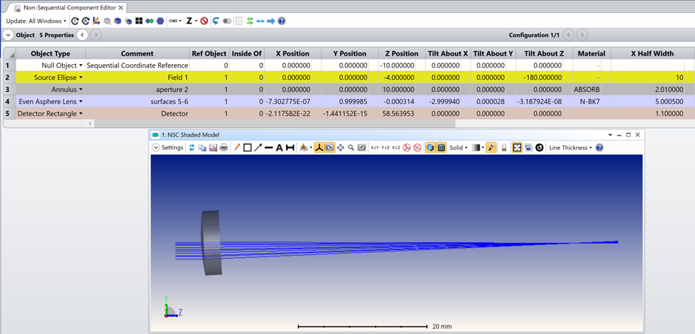
It may be convenient to “clean up” the nonsequential model that results, as shown below. To create the cleaner nonsequential model, I’ve deleted unnecessary rows in the NSCE, and then positioned all parts with respect to object 1 using global coordinates from the sequential model.
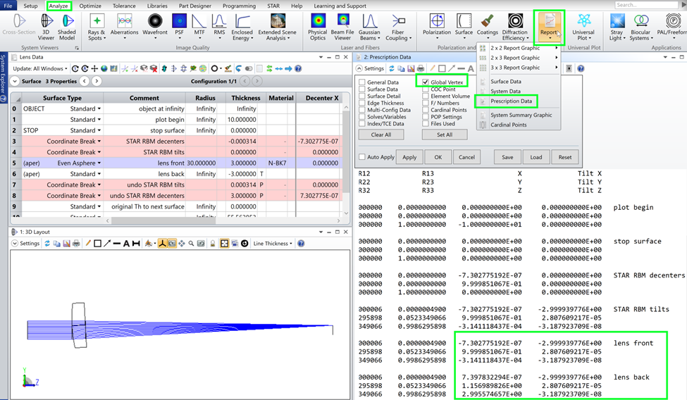
The global coordinates in the sequential model can be retrieved in multiple ways. We can view all the global coordinates in the Analysis / Report / Prescription Data / Global Vertex. I can find the XYZ and ABC coordinates for the stop, the front of the lens, and the image plane, and enter those values directly into the Nonsequential Component Editor (NSCE).
Or, global coordinates can be retrieved using the GLCX|Y|Z|A|B|C operands in the Merit Function Editor. This method is handy because the angle cosines can be converted into angles in degrees, as shown below.
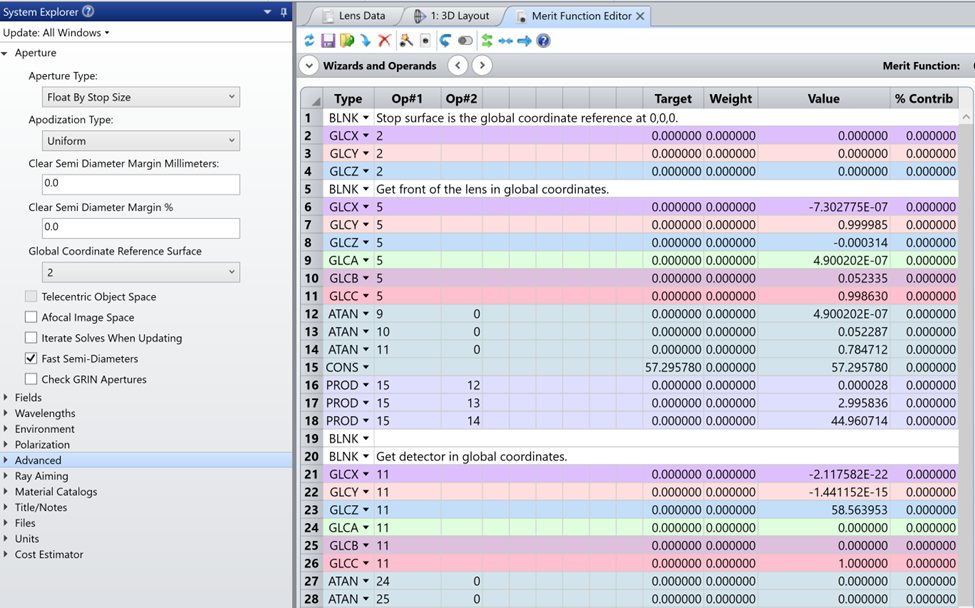
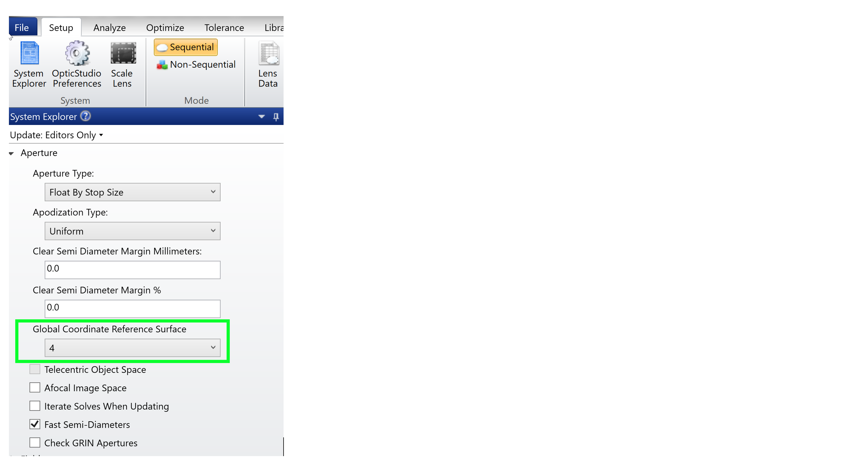
Note that Global coordinates are always defined per the Global Coordinate Reference Surface, found in the System Explorer / Aperture / Global Coordinate Reference Surface, as shown below.