


Released: January 19th, 2021
1 Tools, Features, and Capabilities
1.1 Add Sources and Detectors
OpticsBuilder users may add additional sources and detectors within CAD
OpticsBuilder 21.1 now offers users the ability to add additional sources and detectors to their optical model. This new ability gives users the ability to better analyze their system by adding in additional sources and detectors meant to simulate extreme conditions that their optical product could encounter, such as light source coming from the sun or a detector placed to measure light at the far edge of a field to improve uniform performance. The ability to add both sources and detectors lends functional use for optomechanical engineers to view how their mechanical components affect the optical system with these extreme situations which brings them closer to a functional product before creating any physical prototype. This functionality is available on both the SOLIDWORKS and the Creo CAD platforms. The Add Source/Detector button can be seen in SOLIDWORKS in Figure 1.1.a and the settings can be seen in SOLIDWORKS in Figure 1.1.b and Figure 1.1.c

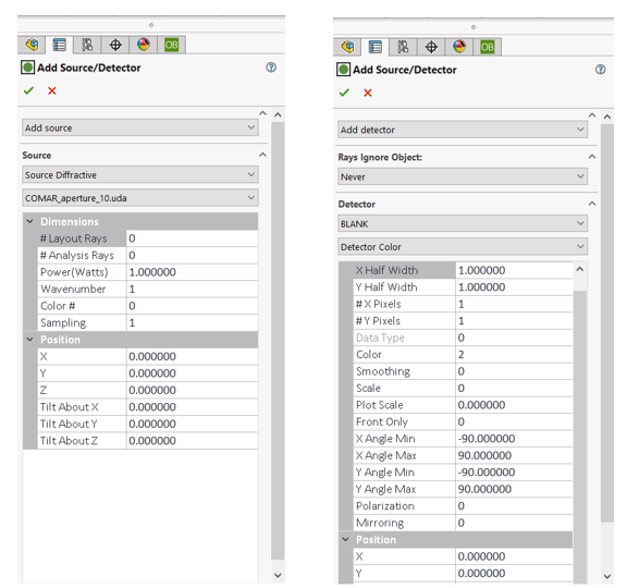
Figure 1.1.c (right) The Add Detector settings are shown
1.2 Full Zemax Glass Catalog Available
Modify the optical design directly in your native CAD platform with the full Zemax glass catalog
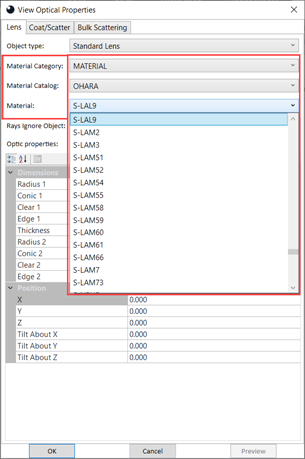
If users load an editable .ZBD file into OpticsBuilder, they can make changes to the optical components, including the material category. This selection now includes the ability to choose the material catalog and the material type to apply to your optical components. This glass catalogue is the same one found within OpticStudio so sharing files between the two programs is easy and flawless. This functionality is available on both the SOLIDWORKS and the Creo CAD platforms. The full Zemax glass catalog can be seen as an option in Creo in Figure 1.2.a.
1.3 Object as Detector Text Report
Users may analyze their system with an object set as a detector
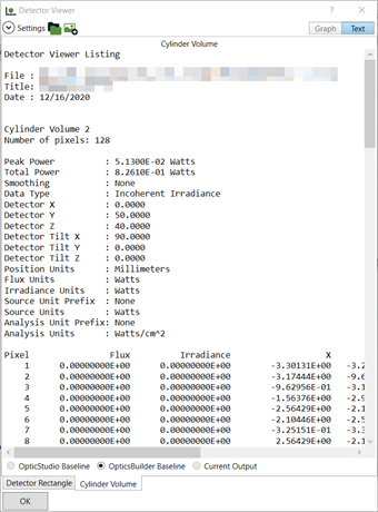
Users have another way to analyze their system by setting an object as a detector. They may view the Results of a Simulation with Object as Detector by selecting “View Detectors” in the Results window. Then users may select the object from a tab at the bottom or by selecting the “Text” report tab at the top. This Object as a Detector text report gives users analysis information with incoherent irradiance. A view of the Object as Detector text report is Creo demonstration of an activated section view of the rays is shown in Figure 1.3.a.
2 Usability
2.1 UI Updates
Improvements to the user interface for ease of use
UI improvements to OpticsBuilder 21.1 include:
- A new tooltip for the Results window/PMP for a better understanding of the setting “Compare Against”
- Updated tooltips were completed for the yellow triangle warning symbol in the Optics Manager. These tooltips give clearer direction on actionable steps.
- The “rays ignore object” option was removed from the editable menu for Sources since this option is not available for sources.
- “Apply surface properties” context menu in SOLIDWORKS has been updated to be similar to the one in Creo.
- Optomechanical components are using the same “Optical Properties” menu/PMP as available to optical components, including the bulk scattering, coat/scatter tabs.
- In all versions of OpticsBuilder for Creo, the default ray thickness has been changed for better visibility
2.2 Updated EULA
An updated End User License Agreement is included
Please refer to the EULA included in the 21.1 release download for more information.
3 Performance and Stability Improvements
OpticsBuilder 21.1 includes the following improvements:
- Beta versions have set expiration dates which typically expire on the next release date, unless otherwise stated.
- Logic has been included to save macrofeature data into the SOLIDWORKS attribute.
- If a mechanical component(s) is present in an assembly before a .ZBD is placed within the assembly, the mechanical component(s) is automatically included into the Region of Interest.
4 Bug Fixes
OpticsBuilder for SOLIDWORKS 21.1 includes the following bug fixes:
- SOLIDWORKS 2020 bugs – Resolutions to improve stability within SOLIDWORKS 2020 include: a system with optical components and STEP parts was failing during Simulation on SW2020 SP3.0, certain icons were not scaling correctly, and a certain object type was hanging for an extended time during import into SW2020.
- Compound lens bugs – Further stability improvements were made for compound lenses throughout OpticsBuilder: SW was crashing when viewing or editing properties for a boolean compound lens with a hole in it, reference geometry was not displaying in the correct position for compound lenses, and SW was hanging during import of a system with a compound lens.
- Detector bugs – Bugs affecting detectors were fixed, including: UI visibility on the graph page of the Detector Viewer was improved, SW was crashing when opening the Detector Viewer for a system containing sources only, the “Rays Ignore Object” flag was skipped after opening the Detector properties PMP more than once in an instance of SW, specification demands to add a source/detector were not executing completely.
- Usability bugs – a modified mechanical component scatter profile saves into the .ZBD file when exported, rays are now cut along a section view that is activated within SW, Rays Ignore Object choice can no longer be changed in a read-only .ZBD file, Simulations no longer fail for a system with mechanical components and trace as a “single part” option ticked, a warning now displays when a read-only optical system is moved because of mates made in SW, a zero percentage for the spot size result is no longer affecting systems with moved components, simulated rays were not showing in the graphics area for certain assemblies, the doublet drawing feature is now producing the doublet drawing and both singlet drawings as it should be, and more…
OpticsBuilder for Creo 21.1 includes the following bug fixes.
- Generating lens drawings – OpticsBuilder for Creo had some bugs fixed relating to generation of lens drawings, including: Adding the “units” line in the drawing, correcting the lambda symbol in the drawing table, cemented/glued objects had an incorrect description in the generated drawing table, cemented/glued objects had item descriptions missing in the generated table, and including some parameters given in OpticStudio into the OpticsBuilder drawing
- Creo crashes – We experienced a few scenarios where crashes would occur when using OpticsBuilder for Creo. The following fixes were implemented: When viewing or editing properties for Boolean compound lens with a hole in the center, when a system is imported with the “Start New Design” option and the generated reference geometry is updated, when a scatter profile is defined for any non-cylindrical lens surface, when using the animate rays feature with partial rays activated, when opening “edit optical properties” on a lens, when the surfaces selection list is cleared by using the “clear selection” context menu, when a system prototype is selected and the “delete” key or any other keyboard key is pressed
- Usability bugs – Using the fold mirror tool sees that rotated components are visible in preview mode, reference geometry is placed in the correct location for compound lenses, the simulation results are now correct when moving a read-only, multiple improvements on functionality when importing secondary optical systems and functionality improvements when optics are placed as sub-assemblies within mechanical top assemblies.