Solved

Cardinal lens model for finite conjugate imaging - Magnification and image space NA


CJ27
  • Visible
  • 24 replies

Hello there friends from the Zemax community,

I have been using a bit the Cardinal lens DLL file to model a perfect imaging lens which images an on axis point  at an optimal paraxial magnification value.

After reading the paper in where the Cardinal lens model is presented: https://opg.optica.org/ao/fulltext.cfm?uri=ao-63-4-1110&id=546054, I set up my system using similar settings to what is described in the section: Finite conjugate imaging from the paper.

Following what is described in that section, I observe that the optimal paraxial magnification value is equal to the ratio of the object space NA to the image space NA.

In my case, my on-axis point is defined in air with an object cone angle of 30 degrees. The image space NA is equal to the NA of a single mode fiber operating at 1.55 microns. (NA=0.12) (At the end I want to model the coupling of light from a point into a SMF) 

With this I obtain the paraxial magnification value that I need, and I optimize the system while using the Cardinal lens’s EFL as variable and by setting my merit function for spot minimization and the found paraxial magnification value as additional target.

 I can get then then results that I want for the on axis point (in terms of the PSF at the image space and the paraxial magnification value) 

Then, once I include an off-axis point (using object height) with an offset of 1 micron, I also obtain a stigmatic image of this point at the image plane, i.e, free of spherical and coma aberration. 

All of this works as intended based on the characteristics of the Cardinal lens.

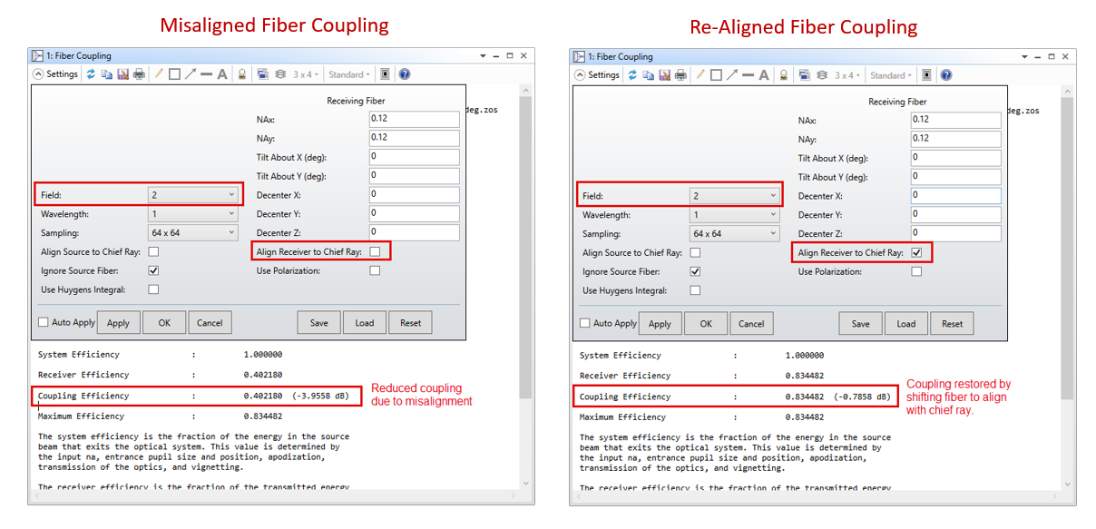
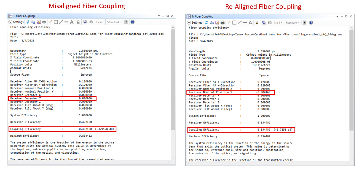
However, I see that by setting the paraxial magnification in this form, my off axis object point is mapped to an image point which is too far from the center of the optical axis (again, I am interested in evaluating the fiber coupling efficiency).

In this case, even if the off axis image point is stigmatic my overlap value has decreased from a value of 86% to 40% for a small object offset of just 1 micron. Obviously this is not what I want.

Having explained all of this, I wonder if it is possible to decouple  the image space height (or magnification in this case?) from the image space NA? From the paper I understand that these two things are related to each other and I dont know if this is a necessary condition for having aplanatic imaging? 

Here is an screenshot for the system I am modeling here:


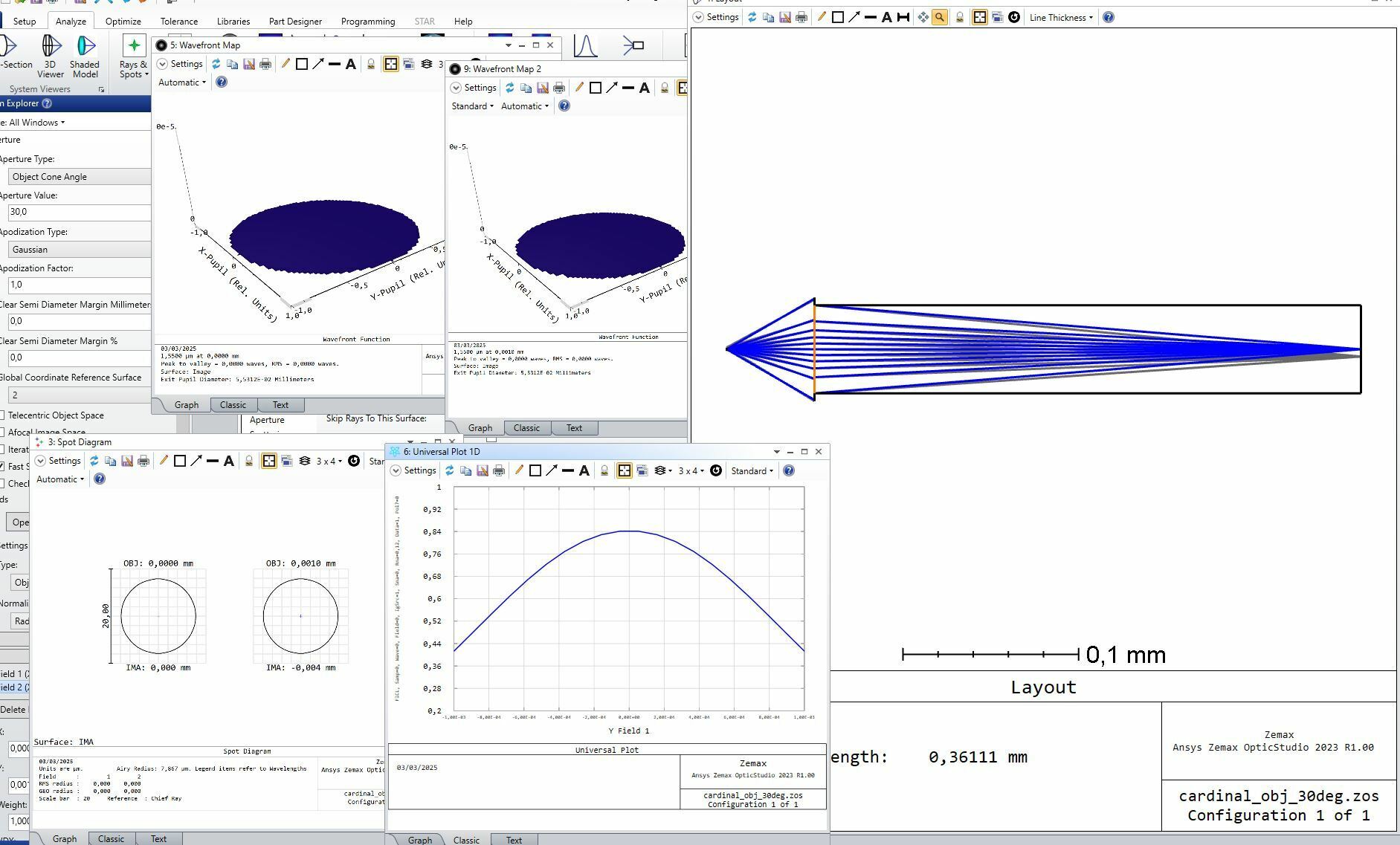
As you might observe, for both field points the performance is diffraction limited and as expected stigmatic. However, from the lower right curve shown there, you can observe how the results from the FCIL operator decrease down to 40% for an object height offset of 1 micron (again, even though the imaging is stigmatic).

Hi @Jeff.Wilde,  do you maybe have some comment on this? 

Any feedback or comment will be welcomed.

Best answer by Jeff.Wilde

Hi ​@CJ27 

I took a look at your model, and everything looks okay to me.  Your paraxial magnification is -4.16, so a +1 micron lateral shift of the source point leads to a -4.16 micron shift of the image point.  Your fiber, however, remains static, so it becomes misaligned and the coupling drops.  The core diameter for an SMF with NA = 0.12 at 1550 nm is ~ 8.2 um.  So, a 4 um shift is a significant misalignment.  (Note: the Huygens PSF is always centered on either the chief ray or the spot centroid, so you will not see the spot shift reflected in the position axis of the PSF cross section.)

If you want to see what the coupling is when the fiber is translated to the chief ray location, then you can check that option and see the result:


You can see where the fiber is located by looking at the data in the Fiber Coupling tool.  The “Align Receiver to Chief Ray” shifts the fiber location and therefore restores coupling:

Regards,

Jeff

View original
Did this topic help you find an answer to your question?

7 replies

Jeff.Wilde
Luminary
Forum|alt.badge.img+3
  • Luminary
  • 505 replies
  • March 3, 2025

@CJ27 :  It would be helpful if you could attach a ZAR version of the model. 


CJ27
  • Author
  • Visible
  • 24 replies
  • March 4, 2025

Hi ​@Jeff.Wilde ,

Sure, here is the ZAR version of the model. 

Thanks for the comments and feedback.


Jeff.Wilde
Luminary
Forum|alt.badge.img+3
  • Luminary
  • 505 replies
  • Answer
  • March 4, 2025

Hi ​@CJ27 

I took a look at your model, and everything looks okay to me.  Your paraxial magnification is -4.16, so a +1 micron lateral shift of the source point leads to a -4.16 micron shift of the image point.  Your fiber, however, remains static, so it becomes misaligned and the coupling drops.  The core diameter for an SMF with NA = 0.12 at 1550 nm is ~ 8.2 um.  So, a 4 um shift is a significant misalignment.  (Note: the Huygens PSF is always centered on either the chief ray or the spot centroid, so you will not see the spot shift reflected in the position axis of the PSF cross section.)

If you want to see what the coupling is when the fiber is translated to the chief ray location, then you can check that option and see the result:


You can see where the fiber is located by looking at the data in the Fiber Coupling tool.  The “Align Receiver to Chief Ray” shifts the fiber location and therefore restores coupling:

Regards,

Jeff


CJ27
  • Author
  • Visible
  • 24 replies
  • March 4, 2025

 Hi ​@Jeff.Wilde,

Thanks a lot for the feedback. I did not know about the re-aligning option.

Well, what I was more wondering about is: Is it possible to beat the limitations in coupling efficiency for this lens configuration? (Given that the fiber and lens are fixed and aligned along the optical axis)

In my case, at the end, I want to design a lens which “corrects” for the possible object offsets in the transversal direction at the object plane. As you mentioned in your comment, for a 1 micron offset in the object plane, my stigmatic image point has a huge trasversal offset, at least for my case, in where I cannot perform any fiber re-alignement, i.e, the fiber and the lens are fixed in space and cannot be re-positioned.

When I read the wikipedia section on the Abbe sine condition (https://en.wikipedia.org/wiki/Abbe_sine_condition#Magnification_and_the_Abbe_sine_condition), there, at the end of the section, it is mentioned:

“This is another way of writing the Abbe sine condition, which simply reflects the classical uncertainty principle for Fourier transform pairs, namely that as the spatial extent of any function is expanded (by the magnification factor, M), the spectral extent contracts by the same factor, M, so that the space-bandwidth product remains constant.”

From this I understand that the Abbe sine condition and its implications on the image points height and NA, are some sort of “fundamental” limit, i.e, that if I want to mantain aplanatism (and get rid of linear coma) in my fiber coupling system, the fact that I am imaging the object ray bundle to a lower NA bundle (to match the fiber NA) implies that there is no way I can “squeeze” more Airy disks or image points closer to each other (since the magnification is the ratio of the image space NA to the object space NA).

Does this need to hold no matter what optical elements I include in between my “initial” source or object and my final image plane? ( meaning that this condition should satisfied for the overall system).  Or does this condition need to hold only for each local object and image planes associated to each cardinal lens?  

What do you think about this? Do you maybe have some suggestion on how could I improve the tolerancing of this ideal aplanatic fiber coupling system (again, in my case performing a fiber re-alignment is unfortunately not possible)

Thanks for the comments and feedback.!


Jeff.Wilde
Luminary
Forum|alt.badge.img+3
  • Luminary
  • 505 replies
  • March 4, 2025

Hi ​@CJ27 

Sorry, no free lunch.  You can reduce alignment sensitivity by broadening the spot size at the fiber input at the expense of lower overall coupling efficiency.

Regards,

Jeff


CJ27
  • Author
  • Visible
  • 24 replies
  • March 4, 2025

Hi ​@Jeff.Wilde,

I see, I got it now.

Any idea about other alternatives to improve the toleracing? What else could I compromise for in this case? (As an alternative to the spot size at the fiber input) I could sacrifice other things to compensate for the toleracing accuracy in this case. 


Jeff.Wilde
Luminary
Forum|alt.badge.img+3
  • Luminary
  • 505 replies
  • March 4, 2025

If all you want to do is collect light, you could use a multimode fiber with a larger core size.  However, if you must use SMF for some reason, then you are most likely stuck with tight tolerances.


Reply


Cookie policy

We use cookies to enhance and personalize your experience. If you accept you agree to our full cookie policy. Learn more about our cookies.

 
Cookie settings