This thread will be used to collect questions before the webinar, and to answer any questions we received during the webinar. Feel free to post your questions! 

Be sure to subscribe to this thread if you want to see additional discussion regarding this topic. The thread will be open to comments until Thursday, May12th. 


Webinar details:

rThe webinar has concluded]

Date: Thursday, May 5th

Time: 6:00am PST & 11:00am PST

Presenters:

  • Hui Chen, Senior Application Engineer
  • Taylor Robertson, Senior Application Engineer

Abstract: 

Complex optical systems require coupling simulation techniques across multiple length scales for accurate design and tolerancing. Extracting the light from nanoscale emissive structures in illumination systems, or propagating light through a mixture of guided and free space components are just a few examples.

Ray tracing approximations break down near the dimension of the wavelength, and electromagnetic approaches are too expensive for larger devices. Traditional methods of linking nanoscale and macro-scale optics required tedious manual file conversions and were prone to error. As a leader in pervasive simulation, Ansys seeks to provide solutions to expediate analysis and alleviate challenges in optical design workflows.

In this webinar we will highlight some interoperability tools between Zemax OpticStudio and Ansys Lumerical that enable engineers to efficiently prototype innovative optical systems.

Watch the recording!

A recording of the webinar is available here: Zemax and Lumerical: Part 1 - From Nano-scale to Macro-scale Optics and Back.


Hello everyone,

Thank you for joining this webinar!

In this thread below, Taylor and I will answer the questions we didn’t get to during the live event.

If you have any further questions, please feel free to ask!

Hui


@Ying

Q: Is POP used for sequential mode or non-sequential mode or both? 

A: POP is mainly a Sequential tool. It’s not available in Non-Sequential mode. The Fresnel propagation method used by POP is not suitable for computing the effects of propagation through arbitrary NSC surfaces. You can read a bit more on this limitation in the help file at The Analyze Tab (sequential ui mode) > Laser and Fibers Group > About Physical Optics Propagation > Propagating Through Non-sequential Surfaces.

-Hui


@Mayuri,

Q: Is the new version of zemax will support solidwork cad file to import for non sequential ray analysis?

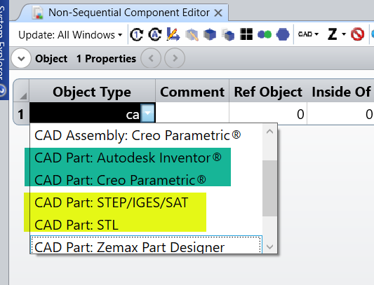
A: OpticStudio supports CAD file import. If you have a static CAD part saved in STEP, IGES, SAT, or STL format, (it can come from any CAD software), you can import them into Non-Sequential mode for ray tracing. However, the CAD Dynamic link option now only supports CREO and Autodesk Inventor.


-Hui


Hi Brian ,

Q: Does Lumerical allow import of thin film design files from TFCalc or Optilayer? / What about fiber tip coatings?

A: I am not familiar with these file formats, and I don’t believe that design files from these tools can be automatically imported.  That being said there are general methods of reading in text, json, or csv files, so it should be possible. Also for your information Lumerical offers similar tools for designing coatings - STACK optical solver. For fiber tip coating simulation you may want to use Lumerical FDTD or EME, which are 3D full wave solvers.


Hello Matthew

Q: During the ray optics optimization, you varied lens curvatures and the air gap given a constant source from the hollow-core fiber. Is it possible to have the geometry of the PCF as a variable? Basically can the optimization tie together characteristics of both size scales?

A: This would require being able to drive Lumerical MODE from Optic Studio, and is currently under investigation.  A similar workflow will be the subject of the next Zemax-Lumerical webinar Registration (gotowebinar.com). That presentation will demonstrate a dynamic link between OS and Lumerical RCWA, for grating and metalens device design and optimization. If you are interested in adopting this proposed workflow, please reach out to support through email.


Hi Ofir,

Q: Is ZBf format compatible with .txt? What is the basis for the ZBF file...ray positions and angles...? could you elaborate? How do the rays at the output of the sequential portion (just prior to entering the fiber) define the gaussian beam profile defined by the POP tool? could you elaborate on this..? trying to understand the POP input/output…

A: The ZBF file supports both Binary format and Text format. You can find a detailed description in our help file at The Analyze Tab (sequential ui mode) > Laser and Fibers Group > About Physical Optics Propagation > Defining the Initial Beam > File (defining the initial beam) > Zemax Beam File (ZBF) text format.

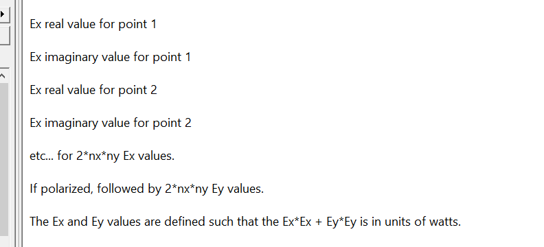
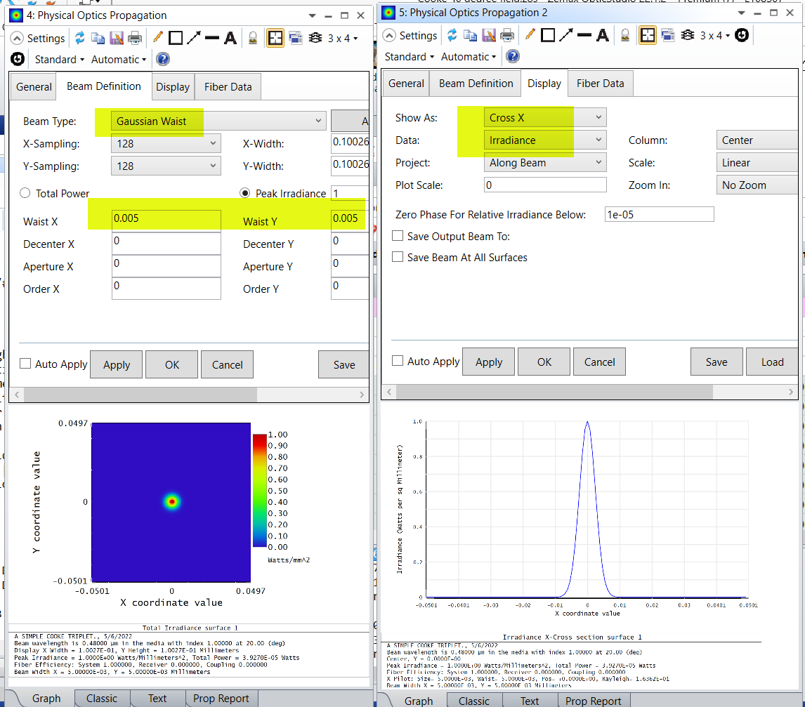
The ZBF file stores the electric field information Ex(x,y), Ey(x,y) on a given surface. Unlike the NSC Source File that stores the rayset info such as ray starting position and direction cosines, the ZBF file describes the beam using its electric field distribution or its mode on a give surface. For example, to model an ideal Gaussian beam that has a waist size of 5 um, you can set it up like below in POP. You can save this beam profile into a ZBF file. In that file it’ll record electric field distribution for every sampling point on this surface. 

POP is the wave model of beam propagation. It uses scalar diffraction theory. For near field POP uses Angular Spectrum Propagation and for far field POP uses Fresnel diffraction propagation. As for how to create your own ZBF file, we have a forum post describing it at How to manually create a ZBF file.

-Hui


Hi @Yisi.Liu 

Q: What is the pro/con between Zemax and SPEOS? Thanks.  / what is the limitation and pro/con of each coupling method (zbf vs rayset)? / Is ZBF for single wavelength?

A: Zemax OpticStudio and SPEOS both have ray tracing capabilities but they have different focuses. Zemax OpticStudio is mainly considered as component level modeling tool, for example modeling of camera lenses, microscopes, telescopes, etc, whereas SPEOS does the system level modeling that can include 3D Environment Integration​, Lighting effect​, Human Vision/Perception effect into your simulation. They are used for different applications. 

As for POP coupling analysis vs ray based analysis, if the light propagation in your system can be well represented using geometric rays, you can stick with rayset to model the beam. For example for multimode fiber coupling where the fiber core size is much larger than the wavelength, you can use ray based model to simulate coupling efficiency into a multimode fiber. However, if you are interested in coherent laser beam propagation and coupling into a single mode fiber where the MFD is on the order of the wavelength, you might want to use POP wave-based model. 

POP analysis runs for a single wavelength at a time and each ZBF file stores the electric information for a single wavelength. 

-Hui


Hello Salah,

Q: How are insertion loss and return loss handled? / How are backreflections and intereference from output optics to input optics handled,  / How are imperfections in optical surfaces and components handled?

A: When using OpticStudio POP to model beam propagation, if you check the Use Polarization box in the POP\General tab, the Fresnel reflection loss at each air/glass interface will be included in the modeling. 

About your second question, POP lives in OpticStudio Sequential mode. This means in POP the beam will follow a single sequence of path as pre-defined in a single configuration in the Lens Data Editor. For POP to handle multiple beam interference, you will need to first model each beam path individually and save the results into a ZBF file, then use ZBFSUM to coherently sum multiple beams to model their interference.

As for the imperfections in optical surfaces and components, this can be handled via Tolerance study in OpticStudio. Tolerance is OpticStudio’s way to systematically introduce manufacturing and assembly error into your design and study performance degradation and manufacturing yield of the as-built system. This can significantly improve product’s time to market.


Reply