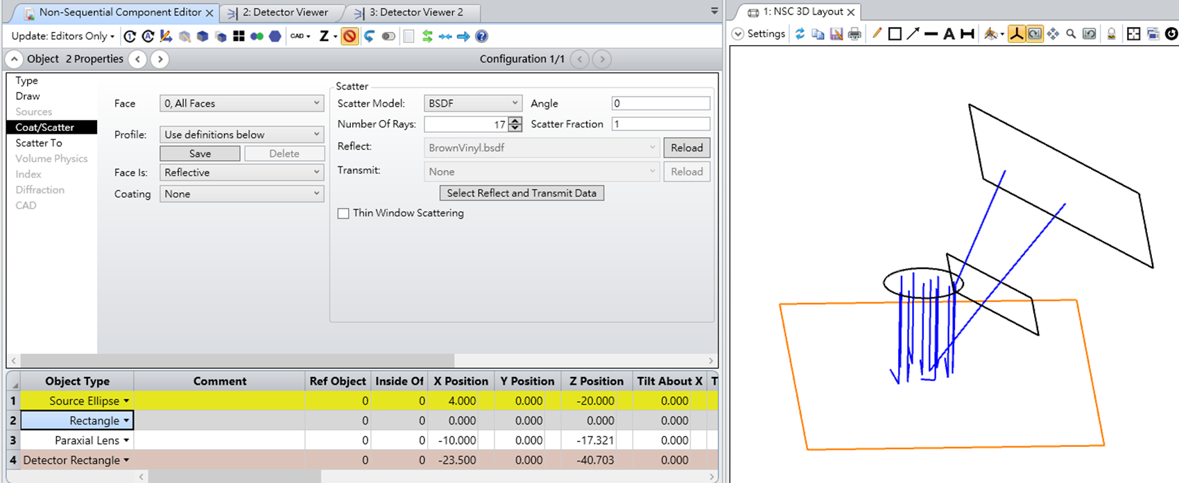
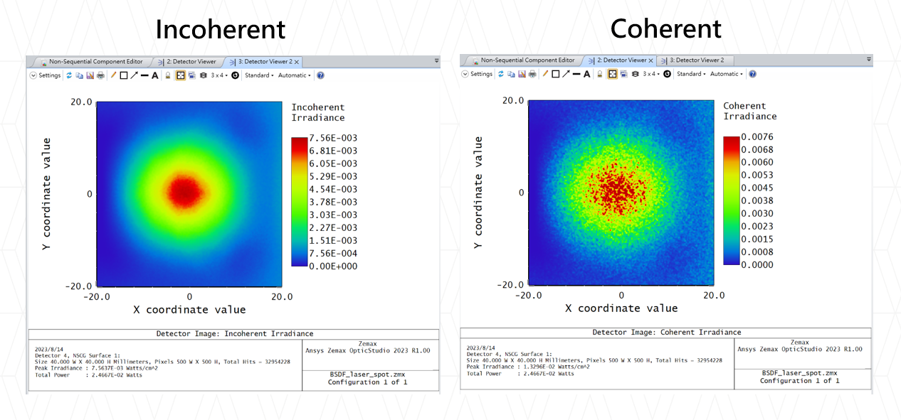
Speckle is created by the interference of multiple, mutually coherent optical fields that have random phases at any point on a detection surface. This could be associated with laser light scattering from a rough surface or from the interference of multiple modes emanating from a multimode fiber. For multimode fibers, it may be best to use POP in a sequential model in which the beam leaving the fiber is modeled as a coherent superposition of LP (or LG) modes. Alternatively, we show here how a simple non-sequential ray-based model can be used to simulate speckle arising from rough-surface scattering.
To model light leaving a rough surface, we can employ Huygens’ Principle and use a set of point sources that are randomly phased over (0,2pi). This assumes the height variations on the surface are large enough to create such a random process. Ideally, we would use a single non-sequential source that emits rays uniformly over some spatial region and within a defined cone angle. However, because we want multiple rays leaving any given point to all have the same phase relative to one another, but random with respect to all other points, a reasonable option is to create a discrete set of point sources that are distributed across a planar “illumination region.” To avoid periodic sampling artifacts, these point sources can be placed randomly within the illumination region. The point sources then illuminate a Detector Rectangle placed some distance away, with the detector set to display the Coherent Irradiance.
Because we will be generating speckle patterns that have fine structure, the point sources should have a small cone angle that provides illumination of the detector only over some small region of interest. Moreover, the point sources should be individually pointed at the center of the detector to maximize the spatial overlap of the beams. This can be done programmatically using ZOS-API. If the distance from the point sources to detector changes, then the pointing angles can be readily updated. A sample Matlab script is attached. Note that the script can be used initially to create a set of point sources, then afterwards the properties of these point sources (the xy-locations, xy-tilt angles, and cone angle) can be modified as needed without having to recreate the individual sources.
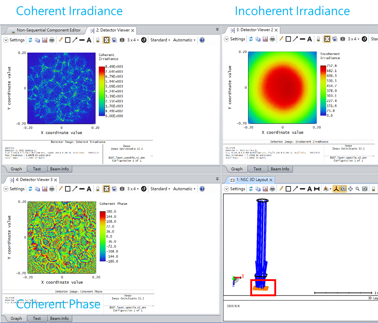
Here is an example in which 50 point sources (0.550 um wavelength) randomly sample a square illumination region that is 0.5 mm x 0.5 mm. A detector (0.2 mm x 0.2 mm) is placed 7 mm away from the source plane. Each point source has the same intensity, but a random phase. A well-defined, fully-developed speckle pattern is observed.
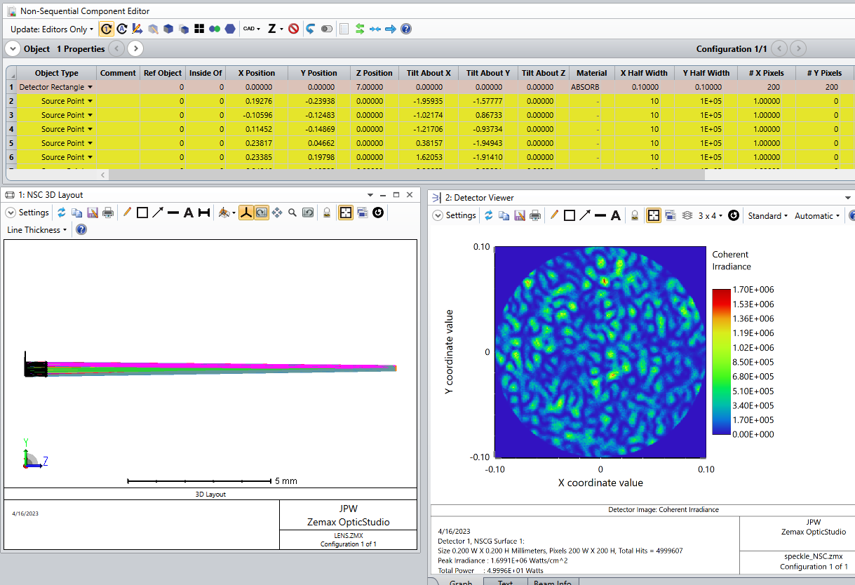
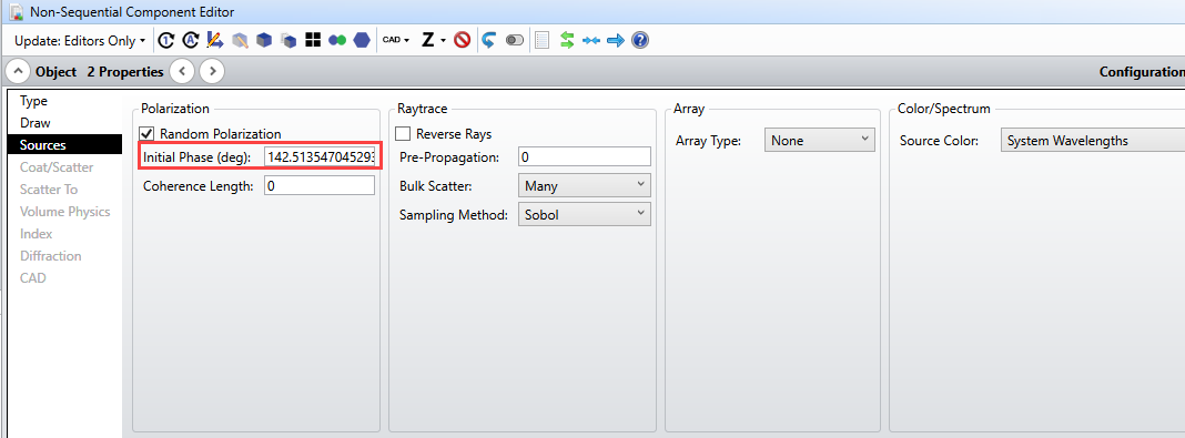
Here is the phase setting for the first point source (which is Object #2 in the NCE).
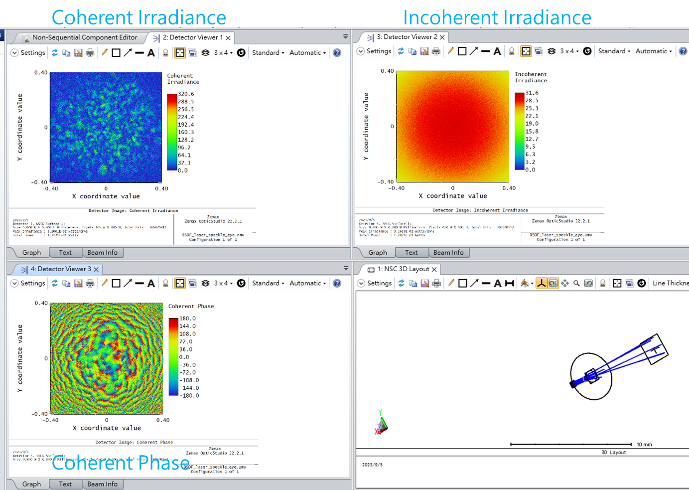
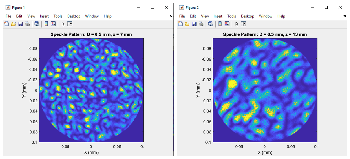
If the propagation distance is increased, the average speckle size should increase proportionately, which is what we find when going from z = 7 mm to 13 mm:
A good reference is Speckle Phenomena in Optics, Theory and Applications, 2nd ed., by J. W. Goodman. In particular, Chapter 5 discusses the spatial structure of speckle.
In the model described here, various changes can be made to the relative intensities and phases of the point sources in order to modify the speckle pattern properties. For example, if the relative phase distribution is not uniform over (0,2pi), as measured from the rays striking any given detection pixel, then the speckle contrast should be reduced so that it is no longer “fully developed.” Presumably, we could also incorporate imaging lenses or other optical components into the path and see how the speckle changes.
Regards,
Jeff


