Solved

Source Diode with circular aperture

  • 8 December 2020
  • 29 replies
  • 968 views


Show first post

29 replies

Dear Dirk, Angel and friends


First of all, I apologize for using your post for my consultation. I am working on the thesis project, and for the design I need the simulation of a 365nm photodiode. However, simulation is not my branch and I am very difficult to process in OpticStudio. In summary, what they would need to obtain is the graphical relationship between the radiance or intensity of the diode according to the distance at which the receiving surface is located.


Blessing,


Oscar

Userlevel 5
Badge +1

Hi Dirk!


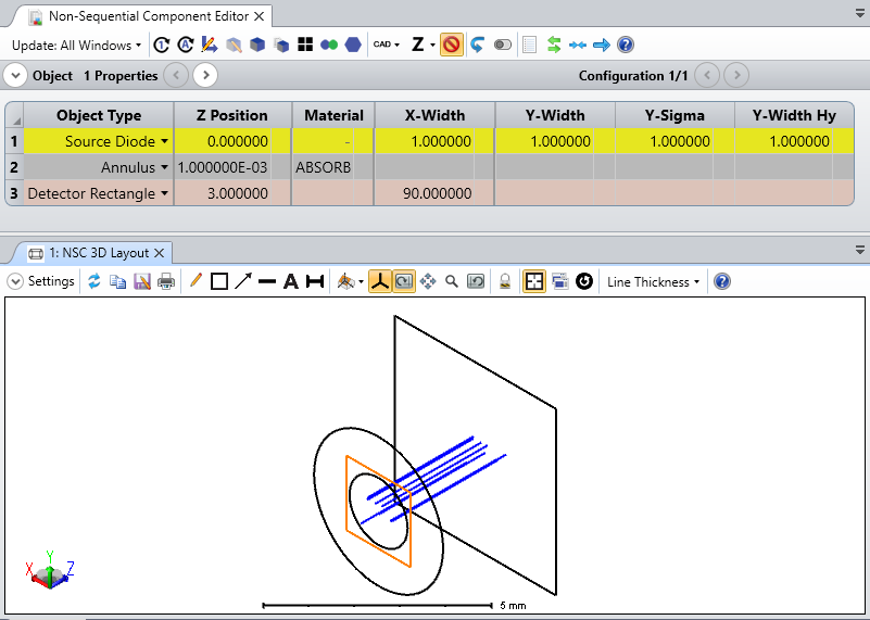
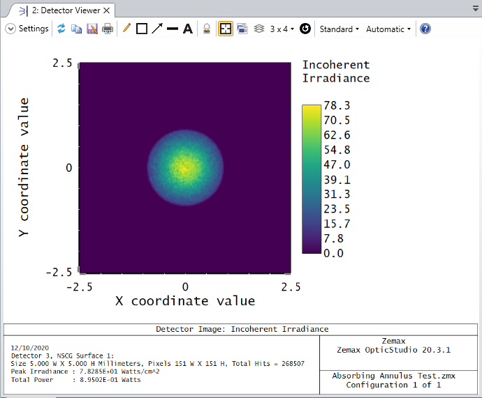
Thanks for your follow-up here. Without being able to see your file, it's hard to say why exactly the distribution of light in your near field detector remains rectangular despite having an absorbing annulus object. One thing you might want to check is that the X-/Y-Width are defined to have the boundaries of the Source Diode itself completely covered by the Annulus object's absorbing area. Depending on the placement of the objects, it might be that the annulus is being ignored, but again, this is hard to say without seeing your file. To demonstrate, though, I've attached a file where the output near field distribution is circular rather than rectangular:


201210-123917-image.png


201210-124003-image.png


If your file still shows some inconsistency, you could certainly share that in this thread or as a new MyZemax case for us to make more specific comments!


As for other resources that cover DLL creation, I think this article does a nice job summarizing all of the key elements that each DLL requires to properly run. Though it covers all different DLL types (Surface DLL, Source DLL, etc.), the link should directly take you to the Source DLL section. After this article, though, we do recommend looking at some provided sample DLLs and their source code (when provided) to get a more in-depth look at the structure of the code.


Let us know how these thoughts work out for you, and thanks again for the discussion so far!


~ Angel


Userlevel 1

Hello Berta,


thanks for your answer. Actually I was using Source Diode with annulus very close to the source (1 micron distance).

But I can still see a weak rectangular shape of the intensity distribution on a detector in the near field. And if I further reduce the distance, Optic Studio provides error messages. So this seems to be a good first workaround but does not work 100% properly...


I have read the Optic Studio manual (p. 494 ff), read the acrticle you recommended, also the help file. And I had a first look into the code of Fiber1.cpp. It looks like DLL programming will take some time, because it's the first time I do it. Can you recommend some more detailed description about Source DLL programming? Or do you know what to do allowing me to put the annulus closer than 1 um to the Source Diode?


Thanks and best wishes


Dirk


Userlevel 4
Badge +2

Hello Dirk,


Most of the sources that are used in OpticStudio are not DLLs, so the diode source code is not available.


However, if you have data  that you would like to implement, you can write such a DLL yourself. Although the diode is not available, there are several types of source DLLs that come with OpticStudio that can seve as a template in the folder \DLL\Sources.


The help file The Setup Tab > Editors Group (Setup Tab) > Non-sequential Component Editor > Non-sequential Sources > Source DLL contains more information on this topic, as well as this article .


Alternatively, you may use Source Diode with an Annulus object to block the unwanted emitting area so that the aperture is circular.


Best,


Berta


Reply