Solved

Simulating collimated laser spot from multimode fiber

  • 25 May 2022
  • 7 replies
  • 1150 views

Userlevel 1
Badge

Dear all,


I am trying to simulate the spot I would have from a multimode fiber  of core diameter d when placed in the focal pont of a lens of focal f on a screen placed at some distance D.

I thought to simulate it with a point object at 0 surface,with 0,00 thickness, place a dummy surface at 1 with thickness f and then place at surface 2 a Lens with thickness D.

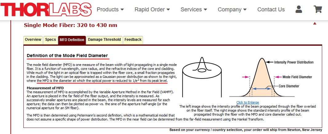
Because I know the NA of the fiber I can use the paraxial Gaussian Propagation tool to define a beam with the rigth M2 and initial diameter and achieve from there dthe 1/e^2 dimensions of my beam.

But...shouldn’t I instead consider the surface of the fiber end like a set of points each one sending rays inside the NA and threat the Spot as an imaging of the fiber end on the screen at D? 

I mean I would place fields at +/-d and then propagate geometrically and finally achieve the spot image n the screen? The fibel tip is not a point and this would make sense

I am a bit confused..can someone help me?

Thanks

Best regards


Gabriele 

icon

Best answer by Jeff.Wilde 25 May 2022, 23:09

View original

7 replies

Userlevel 7
Badge +3

You should consider using the Geometric Image Analysis feature when the source in the object plane is a MMF.  The following thread may be of some help:


Userlevel 1
Badge

Hello Jeff,

Thanks, your reply go straight to the problem.

May I ask you one more question to complete the topic?

To calculate the spot size on the surfaces from a laser  from a MMF I usually used the paraxial Gaussian Propagation tool. This allows to set the dimensions of the starting beam and the M2.

If I have a fiber with a d µm core diameter and and M2 beam parameter product are the results about the beam size on the surfaces given from the tool reliable?

Otherwise I do not understand what the tool is good for.

Thanks for your help

Bests

Gabriele


Userlevel 7
Badge +3

Hi Gabriele,

That’s an interesting question.  Let me think about it for a day or so and get back to you.  Others may have thoughts as well…

Jeff

Userlevel 7
Badge +3

Hi Gabriele,

As promised, I’m getting back to you regarding your question about use of the M2 Paraxial Gaussian Beam Analysis for purposes of finding spot size along an optical path when the source is a step-index multimode fiber.  A few of the issues were not clear to me at the outset, so I spent some time working through the details and decided to write-up my results for sake of completeness.  Please see the attached document.  Hopefully it is fairly readable and self-explanatory.  Please let me know if you have any comments or questions. 

Regards,

Jeff

Userlevel 1
Badge

Dear Jeff,


thank you very much for the very well written piece. It is definitely  much more than I expected as I asked in the Forum.

I have no more questions for the moment. Could be I come however after a while...I need processing time.

Best regards

Gabriele

Dear Jeff,

Thank you very much for your document. In some articles, they recommend using MFD/2(mode field diameter) as the waist. 

We know when fiber core diameter is small and M2 is close to 1, MFD>Fiber core diameter. Which is more accurate, MFD or fiber diameter? Is single mode or multi-mode the same?

Userlevel 7
Badge +3

MFD typically applies to a single-mode beam and is defined at the 1/e^2 irradiance points.  Yes, part of the propagating optical field can exist outside of the core, but for optical modeling purposes the MFD (or half of this value corresponding to the beam radius) should used.  Of course the “waist” is a minimum value of the the beam radius that occurs at one or more particular locations along the propagation direction (depending on the details of the optical system).   


For highly multimode beams, one typically specifies the beam irradiance profile and NA (and M^2 if desired).  For step-index fibers the irradiance profile is typically circular, while for graded-index fibers (say parabolic index profile) the irradiance profile is no longer a flat top.  So, in general, the core diameter of a MMF is not necessarily equal to the output irradiance diameter.  In fact, the output irradiance profile can also vary with launch condition:

Free-space propagation of beams to/from multimode fibers can generally be modeled well using ray tracing as long as diffraction effects can be ignored (which is often the case). 


Lastly, few-mode fibers lie somewhere in between.  In OpticStudio I’ve had success modeling such beams using POP, which allows the starting beam to consist of combinations of spatial modes.


Regards,

Jeff

Reply