Solved

Simulation of optical fiber bundle in sequential mode

  • March 9, 2022
  • 1 reply
  • 1932 views

Dion

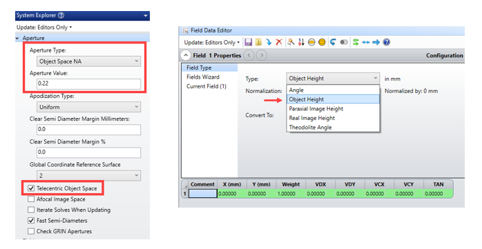
I have an optical fiber bundle with core diameter 910 microns and NA = 0.22 and I would like to make the source as the optical fiber output end with rays coming out of this fiber. The objective of this simulation is to get a collimated rays at the image plane by using a collimating lens. Since I am using a fiber bundle the rays from the farthest point cannot be collimated easily so there would some losses and I need to find how much is overall efficiency of this system.

My question is can I design the fiber output end by providing as many fields points to represent the fiber bundle and assume each point emits a cone of light with NA = 0.22. If not how can I model the fiber end as a source?


Best answer by Jeff.Wilde

You can try using the Geometric Image Analysis feature, which allows the source distribution to be defined by a user-selected shape.  In your case, it is simply a circle.  First, though, to model the output of a multimode step-index fiber (which is what I assume you have), you will want to set the field type to “Object Height,” then set the aperture to an NA = 0.22 and make the system telecentric in object space. 


Now you can use the Geometric Image Analysis feature with a circular source having a diameter of 0.910 mm.


You can select whatever surface you like (probably the image surface) to trace rays from this source distribution to this surface of interest.

View original
Did this topic help you find an answer to your question?

1 reply

Jeff.Wilde
Luminary
Forum|alt.badge.img+3
  • Luminary
  • 491 replies
  • Answer
  • March 9, 2022

You can try using the Geometric Image Analysis feature, which allows the source distribution to be defined by a user-selected shape.  In your case, it is simply a circle.  First, though, to model the output of a multimode step-index fiber (which is what I assume you have), you will want to set the field type to “Object Height,” then set the aperture to an NA = 0.22 and make the system telecentric in object space. 


Now you can use the Geometric Image Analysis feature with a circular source having a diameter of 0.910 mm.


You can select whatever surface you like (probably the image surface) to trace rays from this source distribution to this surface of interest.


Reply


Cookie policy

We use cookies to enhance and personalize your experience. If you accept you agree to our full cookie policy. Learn more about our cookies.

 
Cookie settings