Objective lens implementation from patent


Userlevel 7
Badge +2

Hi everyone,


Our lab is using a Zeiss 20X water immersion lens (Item no.: 421452-9800-000) in a custom light-sheet microscope, and I was trying to perform some simulations of the point spread function (PSF).

I searched for the patent of this lens, and potentially found something relevant at the German patent office (Application No. 10 2005 051 025.6). In this patent, Table 3 describes a 20X water-immersion objective lens with a 1.0 NA and 2.149 mm working distance. I’m copying this table here for your reference:

Surface number Radius Thickness Nd Vd

0

Water immersion
1 -9.039 4.80 1.519 64.0
2 -19.248 4.61 1.597 35.0
3 -9.576 0.40    
4 -101.598 5.00 1.440 94.6
5 -14.227 0.10    
6 64.011 5.50 1.440 94.6
7 -21.754 0.50    
8 58.715 7.00 1.530 76.6
9 -15.181 1.50 1.641 42.2
10 14.227 6.80 1.440 94.6
11 -53.084 0.10    
12 14.539 7.10 1.440 94.6
13 -68.788 1.77 1.561 53.8
14 89.771 0.39    
15 12.320 9.12 1.758 52.1
16 4.800 5.45    
17 -6.587 4.51 1.519 64.0
18 10.441 11.62 1.530 76.6
19 -12.958      


I have used the ZOS-API to populate this data into OpticStudio (code below) to potentially avoid copy/paste mistakes. Then, I made the following changes to my file (that I will also attach to my post):

  • Thickness of Surface 0: 2.149 mm (the working distance)
  • Material of Surface 0: SEAWATER
  • Aperture Type: Object Space NA (dummy STOP on Surface 1)
  • Aperture Value: 1.0
  • Telecentric Object Space
  • Afocal Image Space
  • 3 Fields, uniform Object Height along Y between 0.0 and 0.2 mm
  • F, d, C (Visible) wavelength preset

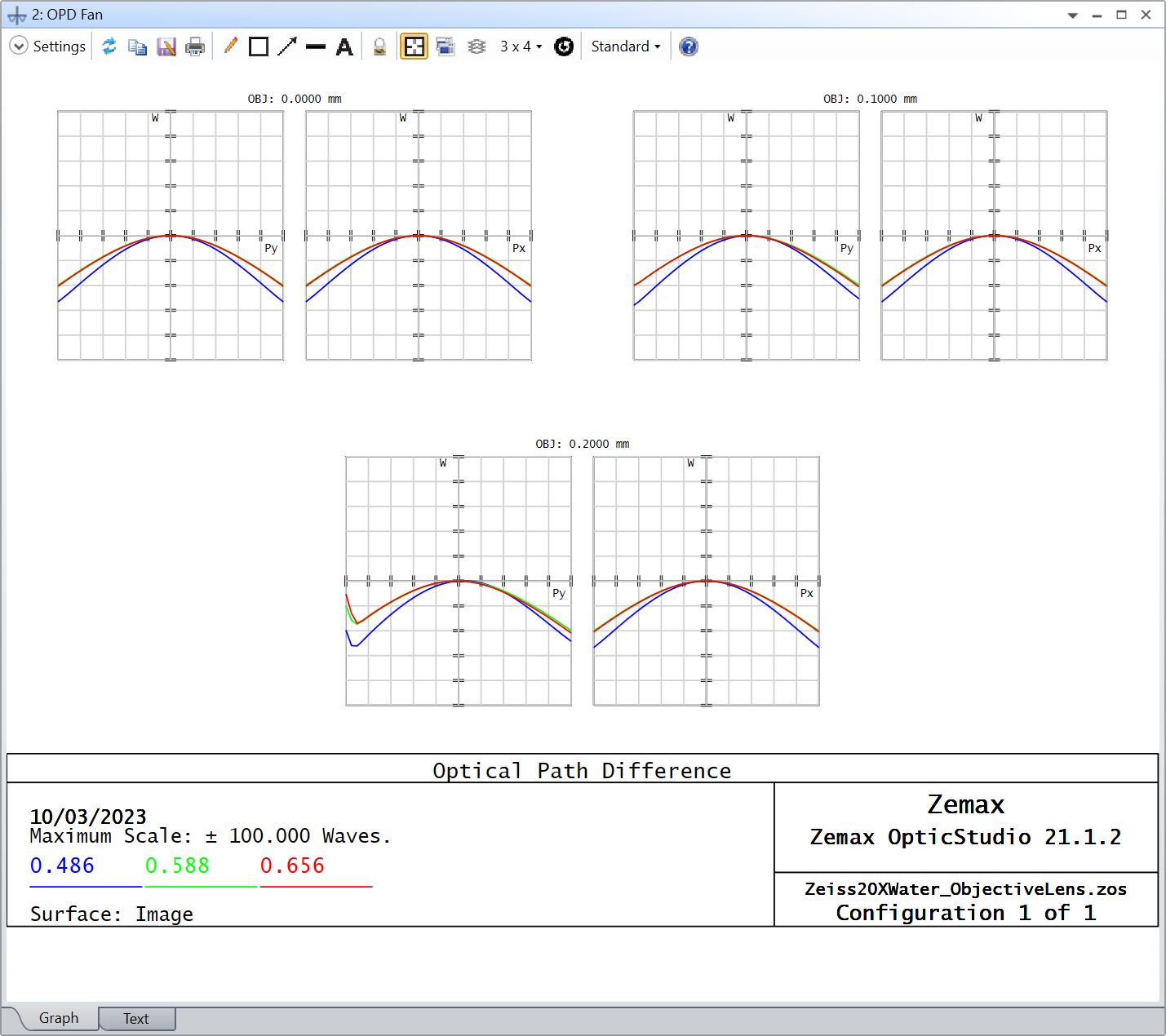
And this is the result:
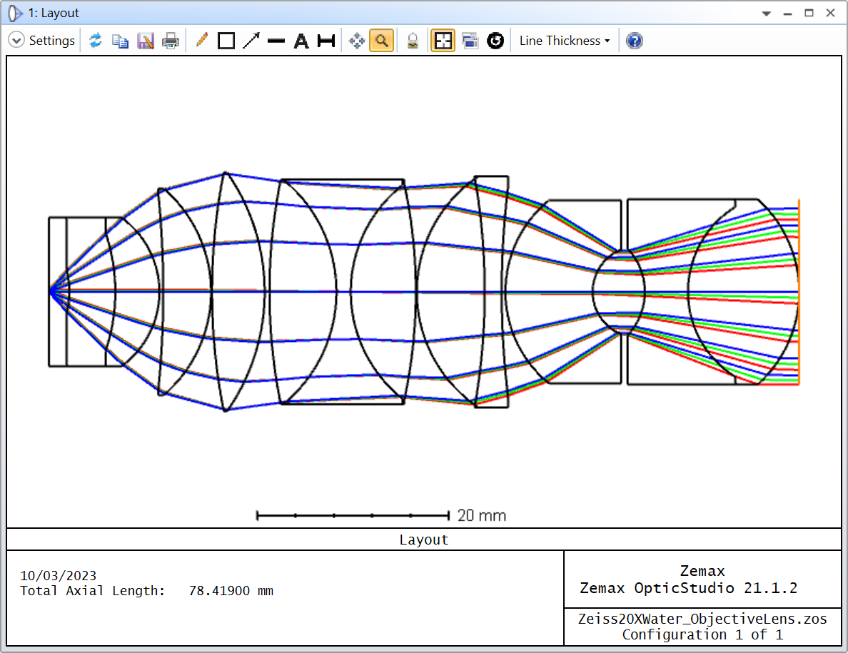
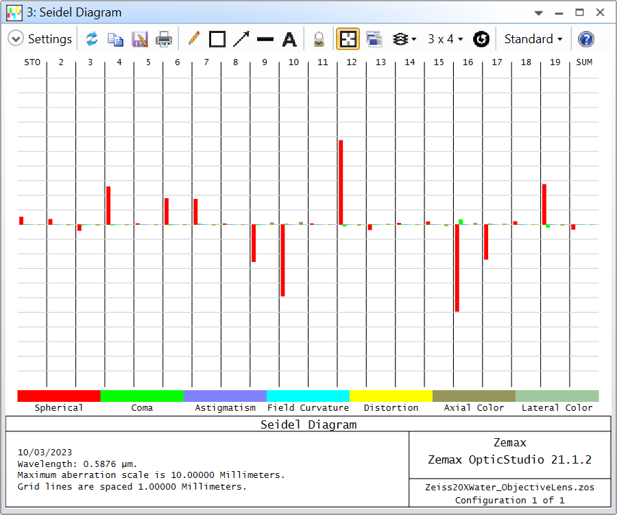
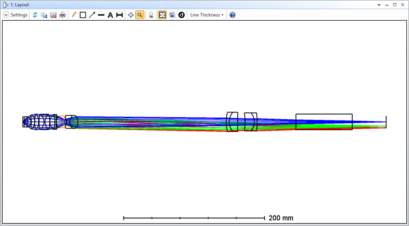
My problem is that the OPD Fan shows huge differences, above 50 waves, and the main aberration seem to be spherical. I was told long time ago that Zeiss used to balance some of the objective lens aberrations on the tube lens in a way that you’d have to buy both lenses from them (you couldn’t just get the objective lens and buy your tube lens elsewhere). But even if that were the case, I suspect I’m making a mistake somewhere. I also know that SEAWATER might not be the material that they used in the patent, but they also don’t specify which one they used. On the plus side, it seems that the STOP is located before the last doublet, or at least that’s where the rays seem constricted.

In the patent, they also show different tube lens design to be used with the objective lenses. I believe Table 4 is the corresponding tube lens, but when I use it, it gets even worst, so I thought it would be easier to troubleshoot the objective lens alone first.

Does anybody have any idea what I might be doing wrong, and how I could improve this design?

Thank you for your help and take care,


David


PS: its not polished, but for those interested this is the code I used after pasting the Patent data into a text file and correcting some abnormalities with whitespaces appearing before some minus signs

# Open text file
patent_text = open(filepath)

# Read every line in the text file
patent_text = patent_text.read().splitlines()

# Insert surfaces at index (surfaces appear before the specified surface)
insert_surface = 2

# Create a Model Glass solve
Surface_1 = TheSystem.LDE.GetSurfaceAt(1)
ModelGlass_Solve = Surface_1.MaterialCell.CreateSolveType(ZOSAPI.Editors.SolveType.MaterialModel)._S_MaterialModel

# Loop over every line and modify the OpticStudio file
for line in patent_text:
# Split the data at every line (or surface)
patent_surface_data = line.split()

# Insert new surface
surface = TheSystem.LDE.InsertNewSurfaceAt(insert_surface)

# Change surface radius
surface.Radius = float(patent_surface_data[1])

# Change surface thickness
try:
surface.Thickness = float(patent_surface_data[2])
except:
pass

# Change surface material
try:
# Change Model Glass parameters
ModelGlass_Solve.IndexNd = float(patent_surface_data[3])
ModelGlass_Solve.AbbeVd = float(patent_surface_data[4])

# Apply solve
surface.MaterialCell.SetSolveData(ModelGlass_Solve)
except:
pass

# Update insert surface index
insert_surface += 1


27 replies

Userlevel 6
Badge +4

Hi David,

I can’t see any problems in what you’ve done. I checked the LDE against the patent -- looks right. I optimized the lens with the first airspace (working distance) variable -- the OPD reduced to 10 waves, still terrible. Wondering if it could be for a 160mm tube, I optimized for a focal image space with front and back airspaces variable -- the optimum air spaces were inconsistent with a valid tube length and the OPD still terrible.

Perhaps the prescription give in the patent isn’t correct.

Userlevel 7
Badge +2

Dear @David ,


Thank you for taking the time to double-check what I did. It seems like I’m not completely crazy yet. I will try some of the other embodiements described in the patent and keep the post updated.

Take care,


David

Userlevel 6
Badge +4

I don’t think my answer should be marked as best just yet, or the question marked as solved.

Userlevel 7
Badge +2

In my mind, you are such a figure in the field that I didn’t think about it when I got your answer. I don’t seem to be able to un-solve the questeion yet though. Perhaps @Sandrine Auriol can do it?

Take care,


David

Userlevel 6
Badge +4

No worries, David. I didn’t realize it was you that marked it solved. I’ve never known how that happened. As for me, I’m not so sure! Now if it was an answer from Mark .  .  .  .

Userlevel 6
Badge +2

Hey David,

I doubt this is the main issue but have you tried to figure out which actual materials are being used by Zeiss? 

I think the Model Index formula OpticStudio uses breaks down for some of the surfaces, especially S2 (nd=1.597, vd=35.0) which is extremely far off the standard glass map line and S4/S6/S10/S12 which have an Abbe above 80 (from the Help Files...”The Abbe number also is limited to the range of roughly 20 to 80”).

Userlevel 7
Badge +3

Patent literature is a minefield, and I have little confidence in the data presented. I really doubt the glass data in particular...specifying just two of the three model glass parameters is naughty but it gets past the patent examiners.

If you do cntl-Z on the model glasses OpticStudio will find the nearest equivalent from the currently loaded glass catalog(s) with any template attached. I’d then try a Hammer with the radii and thicknesses fixed and the glasses set to substitute...worth a try.

  • Mark
Userlevel 7
Badge +2

Hi all,


Thank you for the great suggestions! I was clearly too optimistic when I finally found the patent. I will definitely play around with the materials and see if it leads anywhere. I’ll keep this post updated!

Take care,


David

Userlevel 7
Badge +3

I’ll toss a few thoughts into the ring…  

First, I also agree with Michael and Mark that the limited model glass specification (just index and Abbe number, with no partial dispersion) is likely part of the problem.  Note that the patent actually lists ne and Ve (not the more conventional nd and Vd) -- not sure if that will matter too much if you are going to Hammer on the glass choice anyway. 

Second, it may very well be the case that the tube lens called out in the patent is needed to have the entire optical path work properly.  I wouldn’t necessarily assume that the objective design by itself can be glass-tweaked to become diffraction limited.  I would try both together with glass optimization.  If that works, then a next step could be separate optimization.

Lastly, I think patent designs often try to obfuscate the details, not so much that the patent has a problem getting through examination, but enough so that a direct copy of the design doesn’t work very well.  If I were going to try and hide some details, then the glass specification (or lack thereof) is obvious low-hanging fruit, but so is the number of significant digits for values in the parameter table.  Rounding values to lower precision may also be part of the problem.

Regards,

Jeff

Userlevel 6
Badge +2

I removed the “Best answer” tick.

Userlevel 7
Badge +2

Hi everyone,


And thanks again for all the suggestions. It really shows the strength of this community. I’ve tried to incorporate all that was discussed into the file I’m sharing with this reply.

  1. I’ve hammered the objective lens glasses
  2. Introduced the tube lens
  3. Hammered on the tube lens glasses only with the interlens distance variable (with RAID to constraint for image-side telecentricity)
  4. Hammered on all glasses at the same time
  5. Fixed the glasses and hammered on the radii of the tube lens
  6. Hammered the objective lens radii only
  7. Hammered all the radii

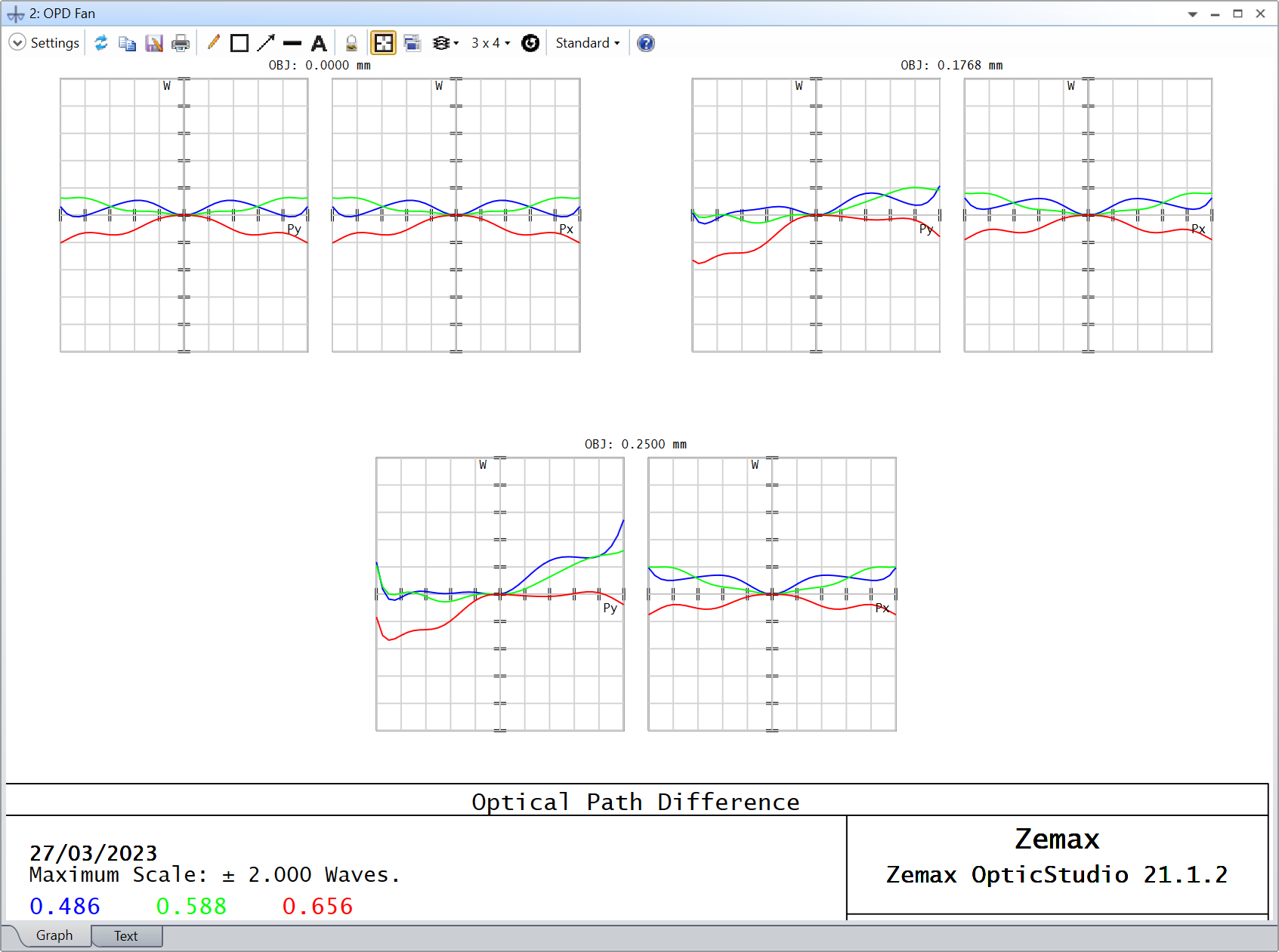
And this is the result:

I’m attaching my file for reference. This is definitely much better than what I could ever come up with before. For the most off-axis field, the Strehl ratio comes at about 0.7.

Can I ask you if there is something else you’d try, such as varying the thicknesses, to refine this design? I’m already quite happy about it and I think I can run my tests, but I’m just oblivious as to whether this is close to the “intended” design or not.

Thanks for all the help again, and I wish you a great week,


David

Userlevel 7
Badge +3

That’s excellent work David. 

If your goal is to get as close as you can to the Zeiss implementation then that’s probably as good as it gets. If you just want the best possible performance, you can continue to refine the design.

Personally, I use patent designs as starting points for further optimization for all the reasons we’ve discussed.

  • Mark
Userlevel 7
Badge +2

Hi Mark,


My goal is to get relatively close to the Zeiss implementation, and as you said, I’ll probably stop here. My next step is to study the point spread function through a simulated specimen. Although those specimen are fairly transparent, I suspect a significant difference in refractive index with the surrounding immersion medium, and I’m curious to visualize it in my simulations.

It’s hard to pick a best answer, everybody has been really helpful. I strongly suggest whoever is reading this to go through the topic in its entirety.

@Sandrine Auriol, I know this is not an official design, but is there a place where we can share such files with the community? I think it could be useful to other microscopists.

Thanks all again, and take care,


David

Userlevel 6
Badge +2

Hi @David.Nguyen ! I’ll have a chat with Allie as we don’t have any specific locations for such files but that could be interesting indeed! I’ll get back to you.

Userlevel 6
Badge +2

@David.Nguyen @Sandrine Auriol With a little more effort on Zemax’s part, this would be an amazing capability to add to the Design Templates.  Either having an “online version” for community contributed designs that is in addition to the ZEBASE files or having the ability to add individual designs from local folders could expand Design Templates a lot.

Userlevel 1
Badge

Hi David,

     I studied some objective patents , most of them didn’t show the specific STOP position. Maybe that’s the reason.


Userlevel 7
Badge +2

Hi @steven.Ou,


It is indeed an issue that the STOP position is rarely reported. That being said, we know the NA. That’s why I setup a dummy STOP on surface one, and used the Object Space NA definition (because I’m modeling the lens backward, it is effectively the image-space NA). Do you think this is not the right approach?

Take care,


David

Userlevel 7
Badge +2

Sorry I meant the specimen-space NA! Somehow I couldn’t edit my reply.

Userlevel 3

Hi all,

I checked the Zemax file and it’s set to telecentric object space, which is a good assumption for a microscope objective.  In that case it doesn’t matter which surface is set to the stop, ZOS will ignore that.  Ray aiming doesn't matter either.  ZOS will launch the chief rays perpendicular to the object, and then they cross the z axis wherever they happen to go.  In this lens the chief ray crosses in the middle of the triplet, which would be a typical location for this kind of objective. That’s probably where the stop was set during design, or they may have forced telecentricity and let it float.

Cheers,

Rick

Userlevel 3

In the file with the tube lens and optimized radii, I noticed that the PMAG is 33. 

I also tried to reverse engineer this lens (with tube lens) after spending way too much time on it I came to the conclusion that it’s pretty much impossible from what’s in the patent.  I was able match every n,V in the patent to either a Schott or Ohara glass, but the performance was still terrible, around 4 waves.  As others noted, the patent doesn’t give partial dispersions. And two decimal places on the index definitely isn’t enough. Since this is an apo with a very high NA it’s going to be very sensitive to the exact index and full dispersion curve (not just partial dispersion which only looks at three wavelengths).

I suspect that one or more of the glasses used is proprietary, and without that information, it’s pretty much impossible to determine the exact performance.

I’d argue that patents like this are invalid since they don’t give enough info to reproduce it but I’m not a lawyer...

If I needed PSF’s for this lens, I’d probably have to just assume an ideal lens, maybe with a little defocus at different wavelengths based on the graph on the last page of the patent.  ​​​​​​

Userlevel 3
Badge +4

Coming late to this party…

  • I have never been able to use a Patent effectively to reverse engineer an optical design
  • I have been able to use SPIE papers to get designs, but in the last 10 yrs, nobody publishes prescriptions anymore
  • Many references (inc. Handbook on Confocal Microscopy) assert that the STOP for most objectives is very close the flange
  • I have used both objectives that are paired to tube lenses and those that are completely corrected without aberration compensation in the tube lens
    • Aberration compensation in the tube lens is not a commercial ploy to get more money from you, it is an effort to relax manufacturing tolerances in the objective lens to get better performance in the system for less money overall
    • Aberration compensation has allowed me to mix-and-match various production runs of the same tube lens, so the compensation is effective at allowing you not to worry about the specific lot number of the objective / tube lens
  • To execute an effective model, I either:
    1. I characterize the actual lens myself
    2. Send it to a 3rd party to measure
    3. Ask the manufacturer for a Blackbox model
      • Some do actually respond to this request
      • Blackbox models are still a challenge to use
      • Often vignetting is present in the objective to improve performance, making the model even more complex to use

For more on objective lenses, see:

https://www.photonics.com/Articles/MTF_Metrology_for_High-NA_Microscope_Objectives/a39883

https://www.nature.com/articles/s41377-021-00663-x

https://link.springer.com/chapter/10.1007/978-3-540-46022-0_2

Userlevel 5
Badge +3

Your first OPD plot looks like the patent's object distance is wrong and the system is out of focus.

The design has a surprisingly terrible flaw in what's going on in the last 3 elements.  That bowtie-looking raytrace through the airspace has ridiculously steep exitance and incidence angles.  A good design never yanks rays that hard, and instead limits RAID and RAED values to 35-40° max.  This reduces high-order aberrations and increases manufacturing tolerances.


Userlevel 7
Badge +3

Fully agree with Mike, but you see this a lot in patent designs. The design as disclosed has flaws, but it does enough to claim the desired IP.

Userlevel 1
Badge

@David.Nguyen 

Hi David

     Looks you got a good design here. Did you have a chance to run the tolerance analysis yet? I’m so frustrated after running the tolerance analysis, couldn’t help thinking how it could be manufactured.👉

Userlevel 7
Badge +2

I somehow stopped being notified of answers to my question after I last commented myself (do you know what might have happened @Allie?). Its only because @steven.Ou tagged me in their question that I got notified by email. I’m sorry I didn’t get to see @PhotonHerder, @Brian.Catanzaro, and @Mike.Jones replies earlier. Thank you all for your valuable contributions.

@steven.Ou, unfortunately, I didn’t run a tolerance analysis on this design. My goal was only to get a better sense for the performance of my microscope, which includes that lens (more details below). Looking at what other people have suggested in this thread, it is likely that we’ll never know how this lens is manufactured.

Lastly, to give everyone a little bit more context. Our lab is using this lens in a light-sheet microscope. Recently, my colleagues have started loading larger specimens and using immersion medium that are not exactly water (often some kind of physiological solution), which of course degrades the image quality. I took some images of microbeads embedded in various concentration of agarose gel with different immersion liquids that highlighted all kinds of aberrations. I wanted to gain a better understanding of what was happening by modelling the microscope in OpticStudio and using a CAD model of our specimen. I haven’t had the time to move this project forward lately, but I’ll be sure to keep you updated with my results.

Thank you again to everyone. I couldn’t ask for a more supportive community.


David

Reply