Hi everyone,
Our lab is using a Zeiss 20X water immersion lens (Item no.: 421452-9800-000) in a custom light-sheet microscope, and I was trying to perform some simulations of the point spread function (PSF).
I searched for the patent of this lens, and potentially found something relevant at the German patent office (Application No. 10 2005 051 025.6). In this patent, Table 3 describes a 20X water-immersion objective lens with a 1.0 NA and 2.149 mm working distance. I’m copying this table here for your reference:
| Surface number | Radius | Thickness | Nd | Vd |
|---|---|---|---|---|
| 0 | Water immersion | |||
| 1 | -9.039 | 4.80 | 1.519 | 64.0 |
| 2 | -19.248 | 4.61 | 1.597 | 35.0 |
| 3 | -9.576 | 0.40 | ||
| 4 | -101.598 | 5.00 | 1.440 | 94.6 |
| 5 | -14.227 | 0.10 | ||
| 6 | 64.011 | 5.50 | 1.440 | 94.6 |
| 7 | -21.754 | 0.50 | ||
| 8 | 58.715 | 7.00 | 1.530 | 76.6 |
| 9 | -15.181 | 1.50 | 1.641 | 42.2 |
| 10 | 14.227 | 6.80 | 1.440 | 94.6 |
| 11 | -53.084 | 0.10 | ||
| 12 | 14.539 | 7.10 | 1.440 | 94.6 |
| 13 | -68.788 | 1.77 | 1.561 | 53.8 |
| 14 | 89.771 | 0.39 | ||
| 15 | 12.320 | 9.12 | 1.758 | 52.1 |
| 16 | 4.800 | 5.45 | ||
| 17 | -6.587 | 4.51 | 1.519 | 64.0 |
| 18 | 10.441 | 11.62 | 1.530 | 76.6 |
| 19 | -12.958 | |||
I have used the ZOS-API to populate this data into OpticStudio (code below) to potentially avoid copy/paste mistakes. Then, I made the following changes to my file (that I will also attach to my post):
- Thickness of Surface 0: 2.149 mm (the working distance)
- Material of Surface 0: SEAWATER
- Aperture Type: Object Space NA (dummy STOP on Surface 1)
- Aperture Value: 1.0
- Telecentric Object Space
- Afocal Image Space
- 3 Fields, uniform Object Height along Y between 0.0 and 0.2 mm
- F, d, C (Visible) wavelength preset
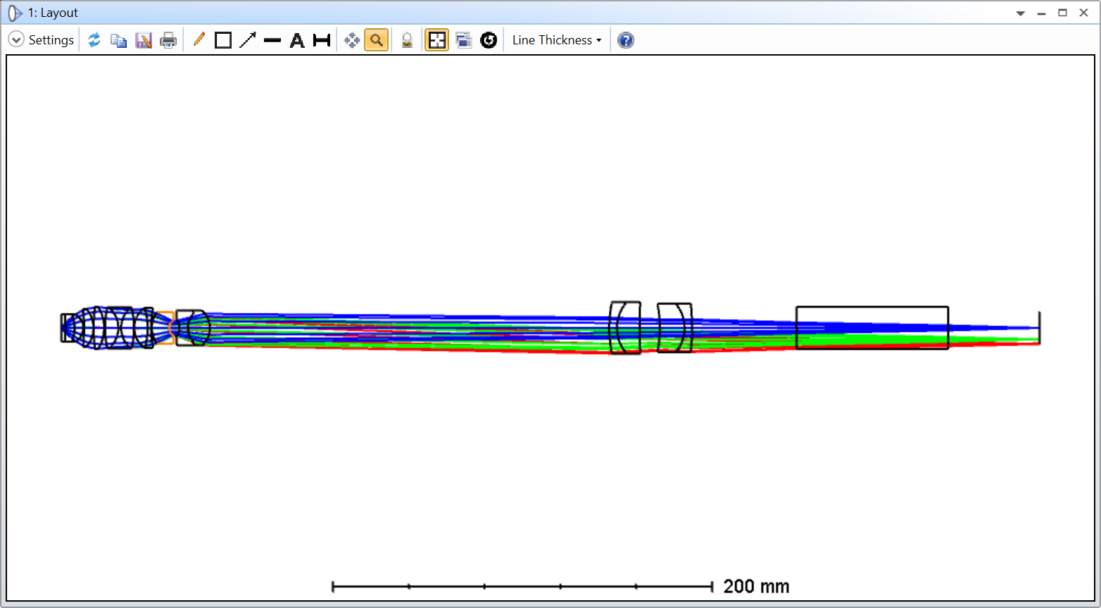
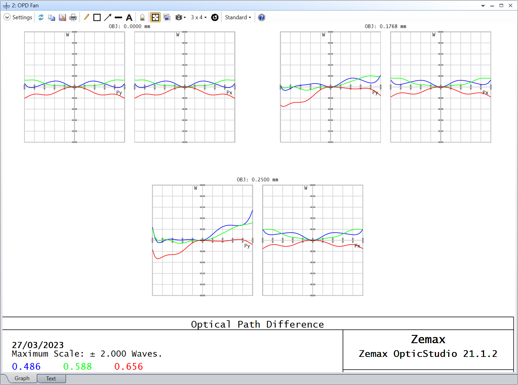
And this is the result:
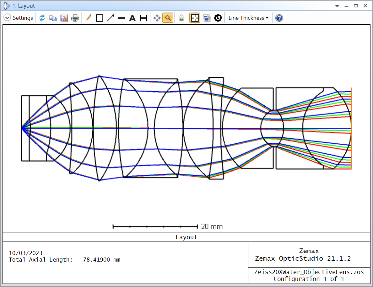
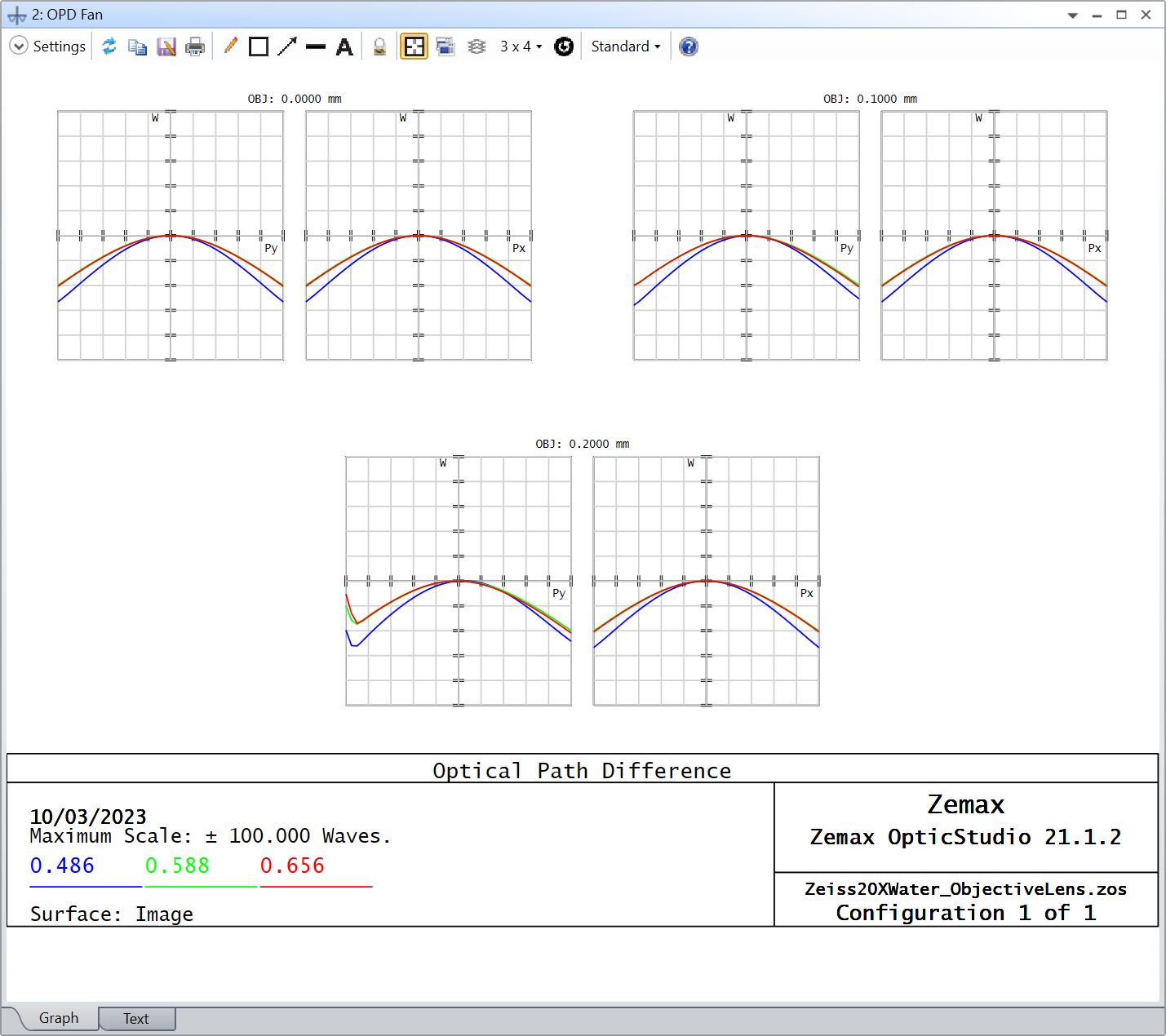
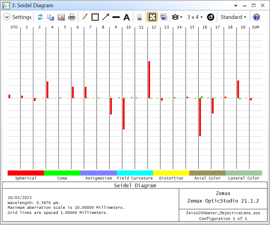
My problem is that the OPD Fan shows huge differences, above 50 waves, and the main aberration seem to be spherical. I was told long time ago that Zeiss used to balance some of the objective lens aberrations on the tube lens in a way that you’d have to buy both lenses from them (you couldn’t just get the objective lens and buy your tube lens elsewhere). But even if that were the case, I suspect I’m making a mistake somewhere. I also know that SEAWATER might not be the material that they used in the patent, but they also don’t specify which one they used. On the plus side, it seems that the STOP is located before the last doublet, or at least that’s where the rays seem constricted.
In the patent, they also show different tube lens design to be used with the objective lenses. I believe Table 4 is the corresponding tube lens, but when I use it, it gets even worst, so I thought it would be easier to troubleshoot the objective lens alone first.
Does anybody have any idea what I might be doing wrong, and how I could improve this design?
Thank you for your help and take care,
David
PS: its not polished, but for those interested this is the code I used after pasting the Patent data into a text file and correcting some abnormalities with whitespaces appearing before some minus signs
# Open text file
patent_text = open(filepath)

# Read every line in the text file
patent_text = patent_text.read().splitlines()

# Insert surfaces at index (surfaces appear before the specified surface)
insert_surface = 2

# Create a Model Glass solve
Surface_1 = TheSystem.LDE.GetSurfaceAt(1)
ModelGlass_Solve = Surface_1.MaterialCell.CreateSolveType(ZOSAPI.Editors.SolveType.MaterialModel)._S_MaterialModel

# Loop over every line and modify the OpticStudio file
for line in patent_text:
    # Split the data at every line (or surface)
    patent_surface_data = line.split()

    # Insert new surface
    surface = TheSystem.LDE.InsertNewSurfaceAt(insert_surface)

    # Change surface radius
    surface.Radius = float(patent_surface_data[1])

    # Change surface thickness
    try:
        surface.Thickness = float(patent_surface_data[2])
    except:
        pass

    # Change surface material
    try:
        # Change Model Glass parameters
        ModelGlass_Solve.IndexNd = float(patent_surface_data[3])
        ModelGlass_Solve.AbbeVd = float(patent_surface_data[4])

        # Apply solve
        surface.MaterialCell.SetSolveData(ModelGlass_Solve)
    except:
        pass

    # Update insert surface index
    insert_surface += 1