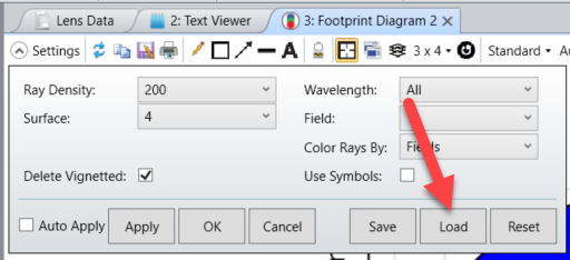
In the manual, it says “Ray Density Determines the number of rays traced across the half pupil; a setting of 10 will
trace a grid of 21 x 21 rays.” What’s the upper limit of the ray density?

I know in the drop down menu, the max setting is 200. When I write my script in MATLAB, I set 'FOO_RAYDENSITY' to '200'. The script runs without any complain.

Later, I read the manual more carefully, and learned the following:

“FOO_RAYDENSITY: The ray density. Use 0 for ring, 1 for 10, 2 for 15, 3 for 20 etc.”

If I follow the series (n+1) x 5, set FOO_RAYDENSITY to 200 means Ray Density of 1005, which means the Zemax will trace a grid of 2011 x 2011 rays. Is my understanding correct? What’s the maximum allowed “FOO_RAYDENSITY” setting? Is it written somewhere in the manual?

Thank you.

Hi Yuan 

I did a quick test. I saved the configuration file of the Footprint Diagram. It saves a file called FOO.CFG in {Zemax}\Configs folder. I checked that my file didn’t have any associated CFG file. For example I used {Zemax}\Samples\LENS.zos and deleted LENS.CFG.

Then I ran the following macro for different values of ray density:

MODIFYSETTINGS "C:\Data\Zemax\Configs\FOO.CFG", FOO_RAYDENSITY, 200

Every time, I tested the result of the macro by clicking on Load:

So it works well meaning that 0 for ring, 1 for 10, 2 for 15, 3 for 20 etc.

I tested 39 and it gives 200.

Then I tried 200 and it stays at 200. 

I hope that answers your question.


Hi Sandrine,

Thanks for your reply. Somehow, when I try to run the macro and then load the cfg file, the ray density setting didn’t change. For example, if I do the following:

  • set FOO_RAYDENSITY to 2,
  • save the macro,
  • run the macro.

I can see the corresponding cfg file is updated. However, when I click the load button, the Ray Density remains at 200.

Am I missing any step?


Hi Yuan

Sorry to ask again but have you deleted the configuration file associated with your file? For example I used {Zemax}\Samples\LENS.zos and deleted LENS.CFG.


Hi Sandrine,

Thanks for the reminder. I found the CFG file associated with the file and deleted it. Now the Ray Density is updated every time I click the load button.

Meanwhile, I have the following findings:

  1. if I set FOO_RAYDENSITY a value above 39, the Ray Density displayed in footprint diagram settings is not updated.
  2. If I set FOO_RAYDENSITY a value above 39, the actual number of rays traced continue to increase.

For example, I see significantly denser rays plotted if I set FOO_RAYDENSITY to 200, and it takes noticeably longer time to generate the plot compared to a setting of 39. I think it is indeed tracing a grid of 2011 x 2011 rays. Meanwhile, the dropdown menu still shows 15 (FOO_RAYDENSITY = 2), which is the previous setting I tested.

It seems that using the macro or ZOS-API, I can continue to increase the ray density. That brings back the original question: What’s the upper limit of the FOO_RAYDENSITY setting? Maybe there isn’t a limit as long as the computer can run?


Hi Yuan!

Interesting. Yes I can see the beahvior you are describing. I will opt for the answer  “there isn’t a limit as long as the computer can run” but I will check with our developers. What kind of ray density were you hoping to have?


Hi Yuan! I got a confirmation from the developers and the Footprint calculation code does not have a limit on the maximum ray density. The interface has a limit because a combo box is used to enter the value. But through the API or ZPL any value can be entered. So be careful when you select a value as a high value can lead to very long calculations.


Hi Yuan! I got a confirmation from the developers and the Footprint calculation code does not have a limit on the maximum ray density. The interface has a limit because a combo box is used to enter the value. But through the API or ZPL any value can be entered. So be careful when you select a value as a high value can lead to very long calculations.

Thanks Sandrine. I was out for more than a week. Thank you for the confirmation.


Reply