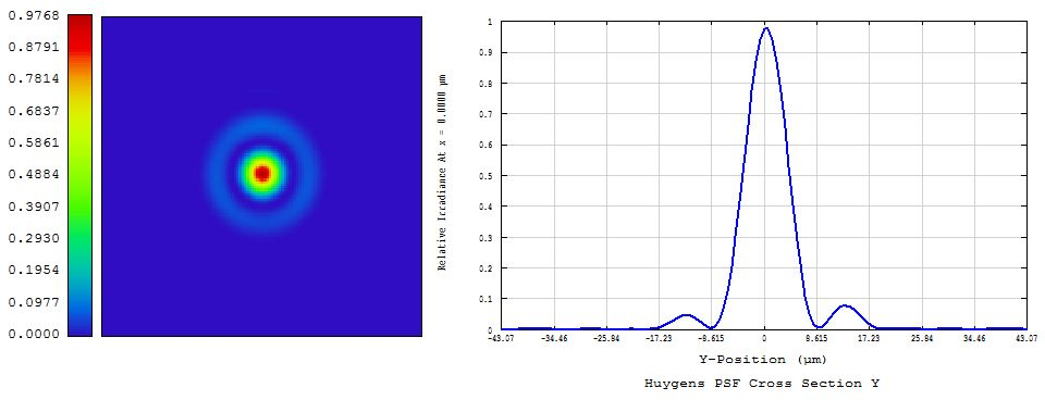
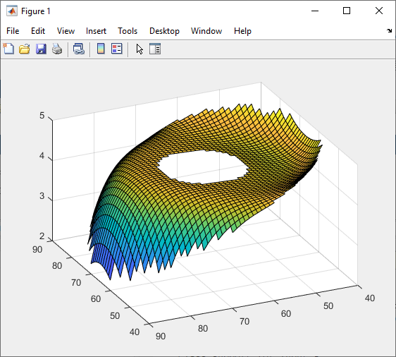
Hi, I followed the recommendations given in other forum threads (ref. 1) or tutorials from Zemax. My optical model consists of a standard Ritchey-Chretien telescope such as f#=6 and fl~500 [mm]. However the PSF obtained using the "Huygens" method (as it is a non sequential system) and POP are quite different. In both cases, the illumination of the entrance pupil is uniform (="Top Flat Apodization"). In addition, I don't see any artifacts in both results that would point to a "bad choice of algorithm" or settings (e.g. under-sampling). Below, please find attached, the spot diagram, the diffraction pattern calculated with the "Huygens" method, and the one calculated by POP, for the outermost position in the FOV (but this is also true for intermediate positions in the FOV). Do you have any comments to explain this discrepancy? Thank you for your help.

SPOT DIAGRAM:
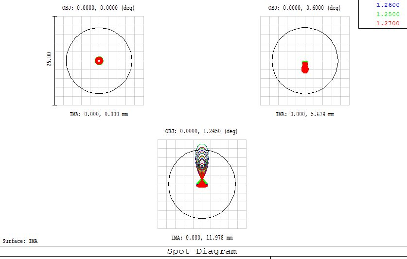
SPOT DIAGRAM

“Huygens” DIFFRACTION PATTERN:

“Huygens” DIFFRACTION PATTERN

“POP” DIFFRACTION PATTERN:
“POP” DIFFRACTION PATTERN


Hi, I've done some new PSF calculations and tests, with different parameter settings. I still see this striking discrepancy. Any comments or help would be greatly appreciated. Thank you very much.


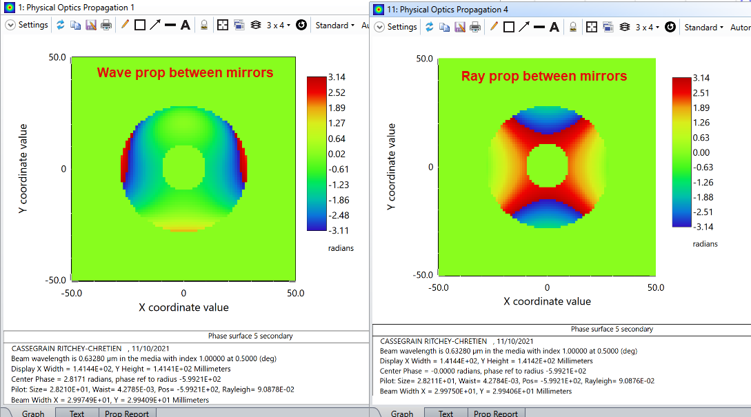
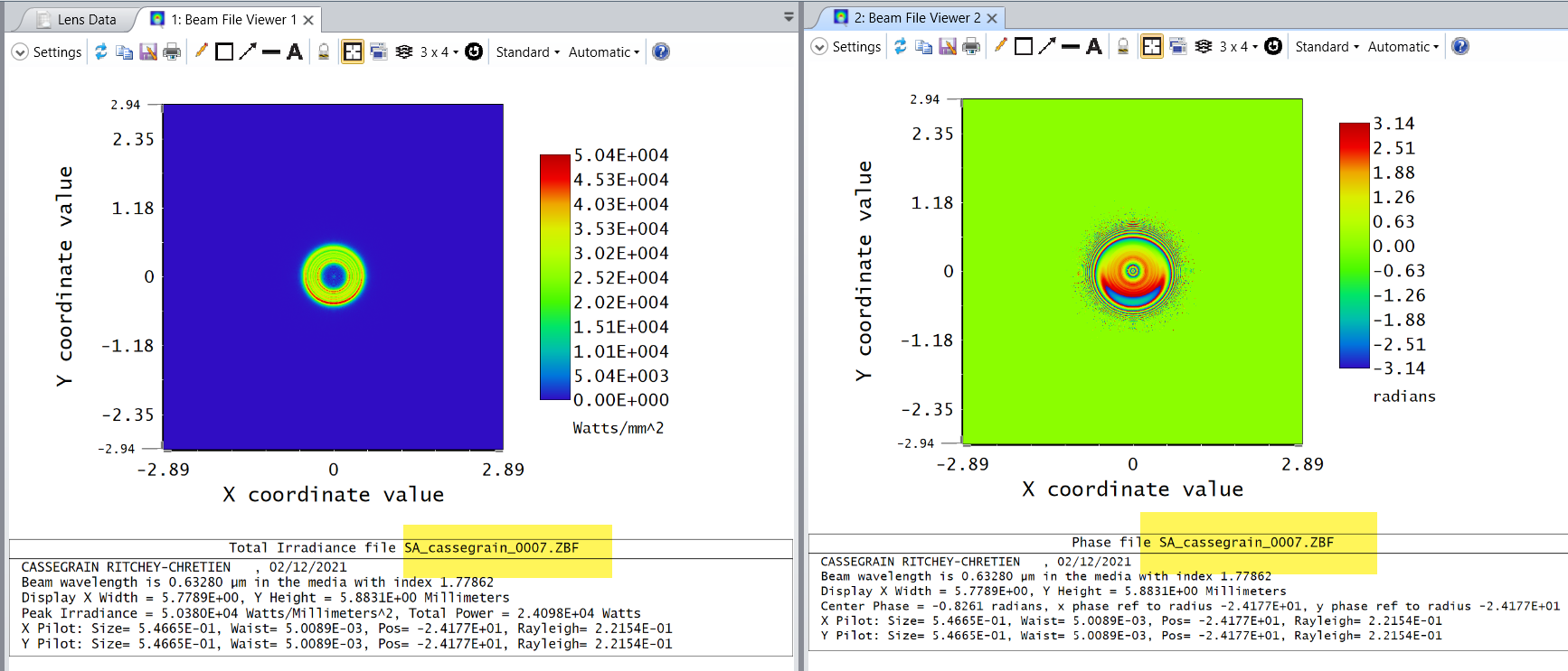
I took a look at the sample file (Cassegrain-type Ritchey Chretien.zmx), added an off-axis field and see a similar effect, although not quite as pronounced.  In any event, if I adjust the POP settings to use rays to propagate from the primary mirror to the secondary, then the discrepancy vanishes (i.e., the POP PSF looks just like the version found using both the FFT and Huygens PSF).  Digging a little deeper, if I use POP to look at the phase of the beam on the secondary mirror surface, I get two different results depending on how propagation between the mirrors is set up. 

Here is the difference between the two phase profiles:


which looks like excess coma -- it arises when using the standard wave-optics propagation setting between mirrors.  Not sure why this is happening, but at least it’s some sort of explanation as to why your POP PSF looks more skewed than the Huygens (or FFT) versions.  It’s hard for me to do any more debugging because most of the computational details are hidden behind the scenes.


Very interesting results! Thank you so much for taking the time to do some experiments on your side to understand where this discrepancy between the diffraction patterns calculated with the Huygens method and the POP method comes from. I think that if the effect is more pronounced in my case, it's because my system is perhaps more compact than yours, less than ~15cm long.

I didn't know that it was possible in Zemax to segment the system in several sections, and to select for each section the light propagation technique used, i.e. "wave-optics", or "RayTracing". It seems here that this is from the primary mirror to the secondary mirror the two methods diverge from each other.

The phase map is very informative. Indeed, it explains why the PSF is very skewed with POP, unlike with Huygens. Based on the spot diagrams, I trust more the Huygens method which is by the way perfectly suited to this optical configuration. Its working principle is well described in the Zemax documentation, as well as its use cases. I have also looked at the chapter dedicated to POP. I have not yet read any fundamental reasons that could explain this discrepancy, or suggest that it should not be used for this kind of system. "Who can do more, can do less", no ? ..  There are different formalisms to model (and approximate) the wave nature of light. I have not yet fully understood the method adopted by Zemax. I just wanted to try and compare the two methods. I would expect POP to be slower, but in the end, it would give the same results. It's still a mystery.

Thank you for your help.


No problem, you raised an interesting question.

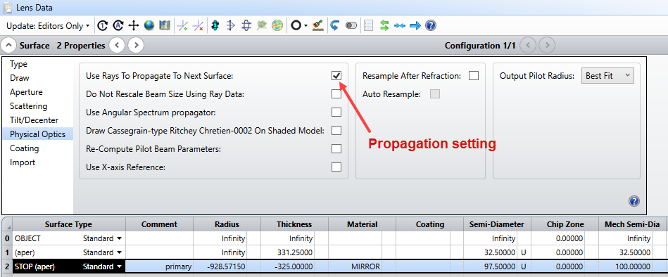
Yes, in POP you can control how the beam propagates from surface to surface.  There is an option to select ray propagation, so that diffraction is neglected from the selected surface, but that’s okay if the propagation distance isn’t very long and beam is far from a focal point.  Here’s an example of selecting ray propagation from the primary mirror to the next surface (which in this model is the secondary mirror):


I agree that the Huygen’s PSF is probably the best choice, although the FFT version should essentially be identical since this is a fairly slow (i.e., large f/#) imaging system.  Here’s a good article by Ken Moore on PSF calculations (but it doesn’t include POP):  What is a Point Spread Function?

The discrepancy with POP is a question for Zemax tech support.  I’m still scratching my head…


Hi, thank you again for these explanations on how to select the "Ray Tracing" option in POP, and thus control the method of beam propagation from surface to surface.

I had read this article you mentioned. It is indeed very helpful to understand how the diffraction pattern is calculated using the Huygens method, i.e. when the beam is decomposed into plane waves that interfere successively to build the final PSF at the image plane.

I will continue to read the chapter dedicated to POP in the Zemax documentation, because this discrepancy between the two calculation methods remains unresolved (contrary to what the tag of this thread indicates..). Thank you.


I agree this is unresolved and am also interested. At least one of these two results is incorrect. I would be really interested in knowing if one is correct, and for the other exactly what about the calculation produced a wrong result.


Hi Chales-Antoine, the POP analysis is based on Fourier Optics, specifically Fresnel propagation (which, strictly speaking, assumes a paraxial approximation, but in practice it works fairly well for reasonably high NA’s, maybe up to 0.3 or 0.4 -- search for “Algorithm Assumptions” in the POP help section for more detail).  The standard go-to reference for this analysis is Goodman’s book “Introduction to Fourier Optics,” now in its 4th edition (see the chapter on Fresnel and Fraunhofer Diffraction).  If you are interested in learning more about the specific details of the way in which OpticStudio implements Fresnel propagation (in addition to what the help documentation says), you can see the chapter “Optical Modeling” by Lawrence:

It’s an obscure reference.  If you have problems finding it, I can email you a pdf version.


Hi David, yes this is a strange discrepancy.  I’ll see if I can get someone in tech support to help out, ideally responding directly to this thread.  At this point I would put my money on the Huygens/FFT result.


Hi Jeff,

Thank you! This information is very helpful as well as the references about the formalism (Fourier Optics, Fresnel Diffraction, and its "Algorithm Assumptions") adopted by Zemax and on which their POP method of calculating the diffraction pattern=PSF is based. I plan to read the POP help section of the Zemax documentation. I would also be interested if you could please send me a PDF version of this "Optical Modeling" chapter by Lawrence.

From the same article you mentioned above (What is a Point Spread Function?), it seems that one of the two "basic"/non-POP methods called "PSF FFT" is based on Fresnel diffraction (unless I am mistaken), and is perhaps wrongly called "Fraunhofer diffraction". The wavefront at the exit pupil is sampled by a grid of rays launched through the optical system which give the optical path difference (due to optical/geometric aberrations) at each point of the wavefront grid. This "wavefront grid" at the exit pupil gives the "delta(x,y)" deviation (which is a function of the position within the exit pupil) to be injected in the exponential term of the Fresnel integral which allows to compute the PSF in the screen/sensor plane. This is at least what I understood of the principle of calculation of this method "FFT PSF". The "Huygens" method is more or less equivalent, it is in a way a trick to calculate the Fresnel integral "backwards", without the Fourier transform...

There may be some confusion (?) due to the fact that all the references/resources cited by Zemax about diffraction are gathered in the same "POP" section, regardless of whether they deal specifically with the POP method or the "Huygens"/"FFT PSF" methods.

It would indeed be very helpful to have some comments on this topic from someone in tech support.

Thank you for your help.


Yes, the FFT and Huygens calculations are related, but the FFT version is more restricted as described in the Knowledgebase article by Ken Moore.  However, the FFT approach is significantly faster.  For low F/# imaging, or systems with image plane tilt, the Huygens PSF is more accurate if sufficiently sampled.

The FFT method is a Fourier transform of the exit pupil field.  This yields the Fraunhofer diffraction pattern of the exit pupil.  Fraunhofer diffraction is a special case of Fresnel diffraction.  Again, the best reference for the basic principles is Goodman, Intro. to Fourier Optics (see the chapters on Fresnel & Fraunhofer Diffraction, and Frequency Analysis of Optical Imaging Systems).


Thanks for the recap of the respective advantages of these two methods "FFT"/"Huygens" and the specific situations in which it is more relevant to use one or the other, as well as for the clarifications about how this method of calculation by FFT works.


Hi Jeff and Charles

Thank you for the interesting discussion here. I looked at the same file used by Jeff and I performed the checks described by my colleague here: https://support.zemax.com/hc/en-us/articles/1500005488641-Using-Physical-Optics-Propagation-POP-Part-3-Inspecting-the-beam-phases

I am basically checking that the phase for each array (ZBF file) is correctly sampled, because this can lead to issues during POP calculations. And I believe this is the problem here.

For each surface, I selected the default properties for POP and then saved the ZBF files. 

To me the issue appears on surface 7. Surface 7 is the surface roughly 500mm away from the 2nd mirror. We can see that the phase is undersampled. I tried higher sampling values but that didn’t help.

When there is an issue with the sampling, we usually recommend to work with the Huygens PSF, which is what you did here.

I can ask one of my colleague to check but I believe that the sampling is the reason of the discrepancy here.


Thanks Sandrine.  I spent some more time looking into this issue, and I think the problem is not one of sampling, but rather just a fundamental limitation of the Fresnel approximation used in POP. 

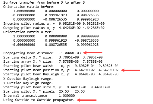
For this telescope model, I placed a dummy surface very close to the primary mirror, just 1 micron away.  Then I used POP to propagate from the primary mirror to this dummy surface, but used ray tracing to go from the dummy surface to the secondary mirror.  All other propagations were done via POP.  The result is a PSF that displays more coma than the result obtained from FFT/Huygens methods.

According the the Propagation Report, going from the primary mirror to the dummy surface is an Outside-to-Outside operation, meaning the wavefront at the primary mirror starts outside the Rayleigh range of the Gaussian pilot beam, is then Fresnel propagated to the waist location of the pilot beam (464 mm away), then Fresnel propagated back to the dummy surface.  

I suspect this Outside-to-Outside calculation introduces a small amount of wavefront phase error.  Indeed, if I use rays to propagate over this 1 micron gap, the PSF changes to match that of the FFT or Huygens result. 

Note that the NA of the beam is highest in between the primary and secondary mirrors (NA ~ 0.2).  While this isn’t particularly large, it is certainly big enough to introduce some residual error since the Fresnel approximation is equivalent to a paraxial approximation (Goodman, Intro to Fourier Optics, 4th Ed., Sec. 4.2.4), and an NA of 0.20 is non-paraxial by about 0.7% ai.e., asin(0.20) = 0.2014, and (0.2014-0.20)/0.20 = 0.7%].

So in this case the more accurate PSF is found using either the FFT or Huygens approach. 


Hi Sandrine, Jeff. Thank you for investigating once again the origin of this discrepancy in the PSFs obtained between these two methods of computation of the diffraction pattern for this telescope model.

The minimum sampling of the beam phase is indeed much more sensitive than for the amplitude. We can clearly see an aliasing effect on the heat map of the phase located at the edge of the spot and its outer rings. However, there is in fact not much energy=amplitude conveyed in these regions where the phase varies rapidly and is poorly sampled. In addition, increasing the sampling resolution does not change anything.

Your test based on the introduction of a dummy surface placed very close to the primary mirror is very convincing. I did not know this calculation trick called "Outside-to-Outside" used by Zemax. Indeed, this technique seems to impart a very small error in the phase of the wavefront, which results in a distorted PSF due to a more pronounced coma. I will also look at my telescope to see what the NA is in the space between the two mirrors.

Of course, the software is not supposed to replace the intelligence of its user, but it would be very useful to advise that for example in this configuration of the optical system, where the aperture of the rays becomes too large compared to the conditions of validity of the POP method, and to the limitations of the Fresnel approximation, the result has chances to be inaccurate. The two methods FFT and Huygens are in conclusion to be used in this situation.

Thank you very much for your time and these very instructive analyses.
Charles-Antoine.


Hi Jeff

Again thank you for your trials.

You are correct. The sampling is not the issue here. Apologies I got it wrong. My colleague had also a look at the file and the issue that I highlighted is just because the zero phase was set for a relative irradiance < 0.001. If I set this to 0, I can see that the phase is properly sampled.

These settings give a good sampling:


After some discussion, the issue here seems to be due to the apertures. We think that probing rays (the rays that we use to calculate the transfer function that transfers the array of electric fields from before a surface to after a surface) don’t work well with off-axis aperture​s. 

I’m going to check with the developers at this point. Thank you for your patience on this.


Reply