Question

Dichroic Mirror in NSC mode Ray Tracing


yfei
  • Monochrome
  • 2 replies

Hello, I have a question similar to post “dichroic mirror in NSC mode”. 


In that question, the supplied example is not in one single configuration, which the emitted light and the excitation light are seperated. I am having trouble simulating the same configuaration but with one dichroic mirror. 

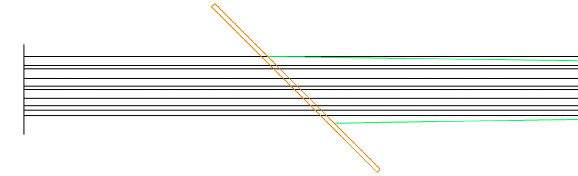
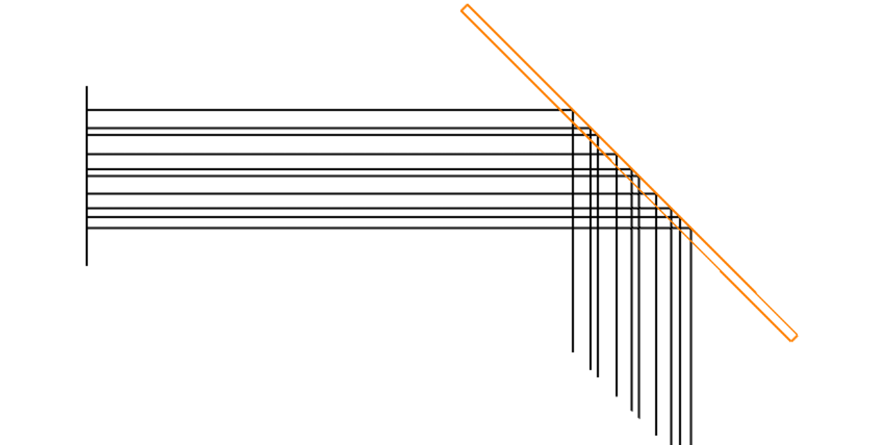
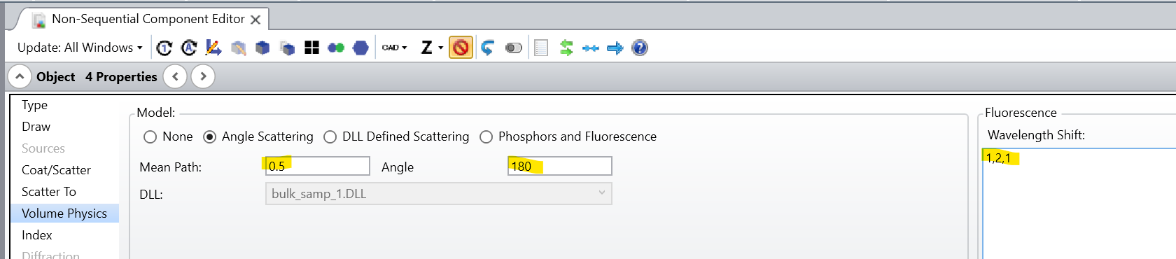
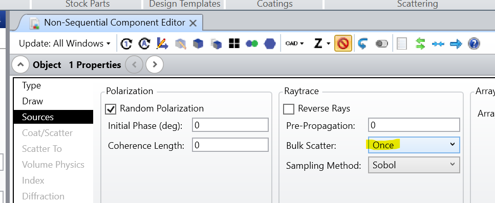
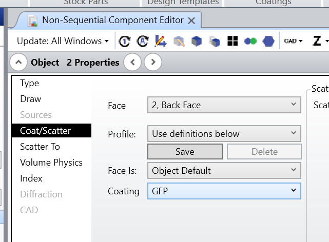
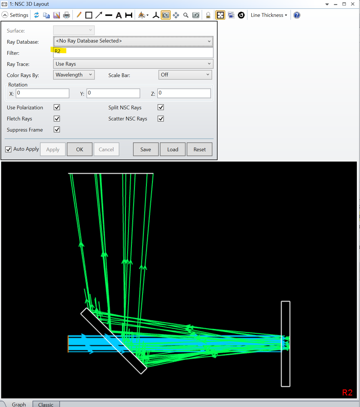
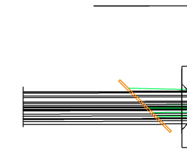
I followed the example “How to model fluorescence using bulk scattering”, but the coating on the dichroic mirror does not seem to function on the back surface (Sample side, Green in the figure). Even if I put a reflective surface at the back surface, the incoming ray (black in the figure) from the source side will hit that surface and reflect away. How should I avoid this sitation? 


I would like to have the source sending ray transmitting through a 45 degree dichroic mirror, hitting the sample, reflect back to the other surface of the dichroic, and reflect to 90 degree respect to source (upward in the figure). Is that possible? It seems to be an easy task, but I don’t have a solution. 


Thank you for your help. 


3 replies

David.Nguyen
Luminary
Forum|alt.badge.img+2

@yfei 


It seems to work for me. Since I’m not sure what you tried exactly, I cannot say what went wrong. Perhaps I am misunderstanding the question.

This is what I think you are after (rays are colored by wavelength):

I used the case of EGFP with an excitation of 0.488um that goes through the dichroic and causes fluorescence at 0.510um in the vertical Rectangular Volume on the right-hand side of the NSC 3D Layout. The fluorescence is then reflected at the dichroic thanks to its coating and is terminated on a horizontal rectangle at the top of the figure.

If that’s what you want, then here are the steps I followed:

  • Define a “GFP” coating (transmit shorter than 0.499um, and reflect longer than 0.500um)

TABLE GFP
ANGL 0.0
WAVE 0.499 0.0 0.0 1.0 1.0 0.0 0.0 0.0 0.0
WAVE 0.500 1.0 1.0 0.0 0.0 0.0 0.0 0.0 0.0

  • Apply the coating to the back face of the dichroic
  • Apply a Filter String in the NSC 3D Layout to only show rays that have reflected on the dichroic (R2 in my case)

I am also attaching my file here for your reference.

Take care,


David


yfei
  • Author
  • Monochrome
  • 2 replies
  • March 17, 2025

Hello, David. Thanks for the answer. 


Latest Update: I was able to correctly have the rays reflected off the dichroic mirror. The solution was to check Split NSC Rays. Could you please explain why this was the critical thing? 


Thank you so much. 


---------------------------------------------------------------

I understand how you did this and I tried to replicate the same sturcture with some modifications: 

  1. Used 910nm instead of 488nm 
  2. Used mie scatter instead of bulk scattering
  3. Added a few piece of lens after the dichroic mirror to simulate an objective

The coating table I wrote is:  full reflectance for 510nm, and tranmission for 910 nm. 
TABLE GFP910
ANGL 45
WAVE 0.510 1.0 1.0 0.0 0.0 0.0 0.0 0.0 0.0
WAVE 0.910 0.0 0.0 1.0 1.0 0.0 0.0 0.0 0.0
 

Somehow this will not allow me to have a reflective ray from the dichroic. The layout will look at the following graph. Do you happen to know what the problem would be? 


Thank a lot. 


David.Nguyen
Luminary
Forum|alt.badge.img+2

@yfei 


Hard to know like this, could you upload an archive?

Take care,


David


Reply


Cookie policy

We use cookies to enhance and personalize your experience. If you accept you agree to our full cookie policy. Learn more about our cookies.

 
Cookie settings