Solved

Approach to find EFL while having a fixed BFL


Userlevel 3
Badge

Hello,


Starting from the model IR Zoom Lens, 85-205mm found in Design Templates in Zemax Libraries, can you please show how to customize the model properly to have a desired EFL? I have a fixed BFL as a costraint and I have 3 number of fields from 3 to 25 degrees.


Thank you in advance, any help is appreciated


Onder.


icon

Best answer by Sahil 28 May 2021, 16:48

View original

10 replies

Userlevel 3
Badge

Hi Onder,


Add the requirents for EFL in Merit Function editor, fix BFL and optimize the system.


If you don't have design experience it can be enough hard to make a good zoom system. It looks that it can be simpler to find a designer for this task.

Userlevel 4
Badge +1

Hello Onder,


Thanks for posting in Myzemax forum! 


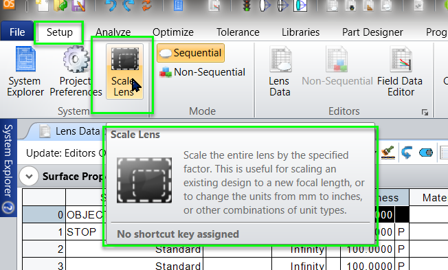
There are two ways to customize your model with desired EFL conditions applied.


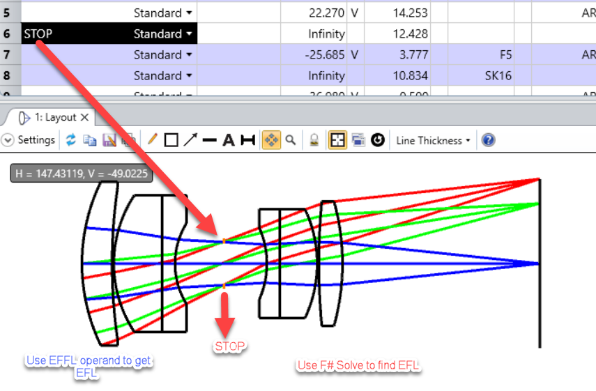
1st Case : So if you want to find EFL of lens after STOP , then you can find EFL by using  solve type F#.


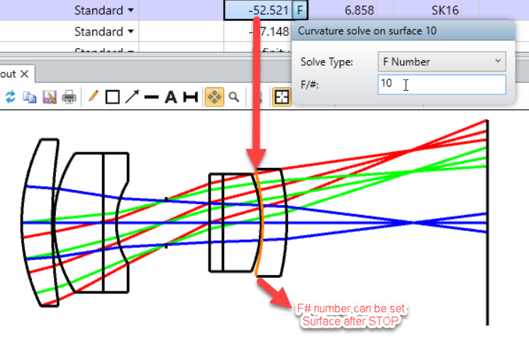
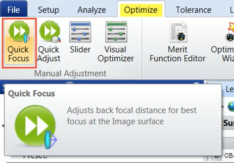
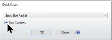
Then radius will automatically adjust for F# =10 .Then you can choose  Quick Focus in order to get proper Thickness of lens with desired EFL


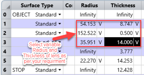
2nd Case : Another way to find EFL ,If your lens lies before STOP then make the parameter radius and thickness to variable. 


In merit function editor ,select image quality and Boundary values . As boundary values is suggestions to zemax suppose what could be maximum thickness of lens should be if you have radius of curvature of -20 .


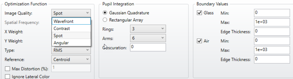
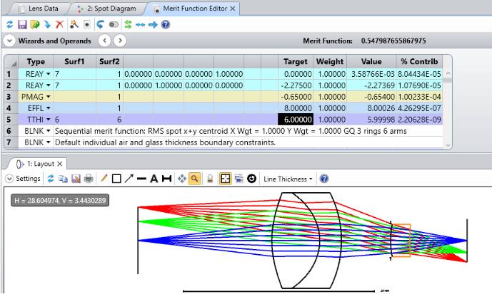
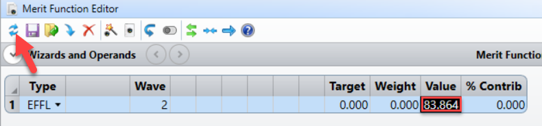
After selecting both optimation function and Boundary values.Please select Optimization operand EFFL in merit function editor and select the desired wave and update it . You will get the EFFL value


Please feel free if you have any question.


Regards


Sahil


Userlevel 4
Badge +2

Hi!

You can also find a design base similar to what you want, and then scale it. 


Then you can do the optimization from the scaled starting point.

-Thomas

Userlevel 3
Badge

Sahil and Thomas Thank you for your invaluable contributions, I will be trying these suggestions at first chance I get.

Badge

Thanks everyone for a great and brief description on the given topic.
I have one question related to the same topic. I have done a design, I have optimized my design for EFL and magnification but unfortunatly my BFL is not matching with respect to my requirement. 
Can you please help me out that which operand should I use to get the required BFL without disturbing the other requirements?


Thanks 

Ashok

Userlevel 3
Badge

Hi…

TTHI operand at last surface thickness would work fine to achieve desired BFL!

Thankyou. 

Badge

I have tried this. Need to maintain TOTR as well.

Please check the below zemax fille want to optimize for 9 mm BFL.


Thanks

Ashok

Userlevel 3
Badge

Zemax file looks good.

I have tried with TTHI on 6th surface and initial merit function is acheived till 6 mm BFL. After 6 mm BFL conic of aspheric surfaces are going to very heigh value which cause manufacturaing diffucuilty!


Check if you can live with 6 mm focal length, otherwise optics configuration needs to be modify!

Thankyou.

Badge

Thank you for giving your time. It was really helpful my TOTR got got reduced but anyway I’ll manage that.

  1. Have one question up-to how much conic surface we can go and can be manufactured easily?
  2. If i want vary the magnification in this design without changing the Lens parameter just want to change air thickness between the lenses, object to lens and lens to sensor/image. Then what should i do?
  3. Best way of optimization with respect to spot size for various field?

Thanks

Ashok

Userlevel 3
Badge

To your concern…

  1. As long as difference between vertex ROC and Best Fit Radius is within +,- 1 or 2 mm for given conic constant, it will not cause significant manufacturing difficulty. You can check the best fit radius in Sag table for a particular surface.
  2. For finite conjugate system magnification mainly depends on u (object distance) and v (image distance) these thicknesses you can control to desired values using any thickness operand.
  3. My approach is always to set aperture and fields from detector side (like filed points “paraxial image height”) and optimise the system with desire specification. But any how, any method of optimization will hold good either spot or wavefront criterial both are interrelated.

Thankyou.

Reply