Ellipsoid object DLL

  • 5 July 2023
  • 5 replies
  • 95 views

Userlevel 7
Badge +2

Hi all,


I’ve seen a few discussions about ellipsoids in non-sequential mode. Notably, @David has shown how the Standard Lens object could be used to build ellipsoids with at least one axis of rotational symmetry in his remarkable answer to the post: Modelling an ellipsoidal volume in non-sequential mode. The Help File also has a section called “Modeling an ellipsoid with the Biconic surface” (The Setup Tab > Editors Group (Setup Tab) > Lens Data Editor > Sequential Surfaces (lens data editor) > Biconic), and the Biconic Surface is also available as a non-sequential object. However, I did not manage to recreate the ellipsoid as depicted in the Help File, which is certainly my fault. In light of the above, I thought it would be a good idea to program a DLL for an ellipsoid object. At the very least, it should have some educational value. You can find the current result of this work in this repository: https://github.com/Omnistic/ellipsoid_object.

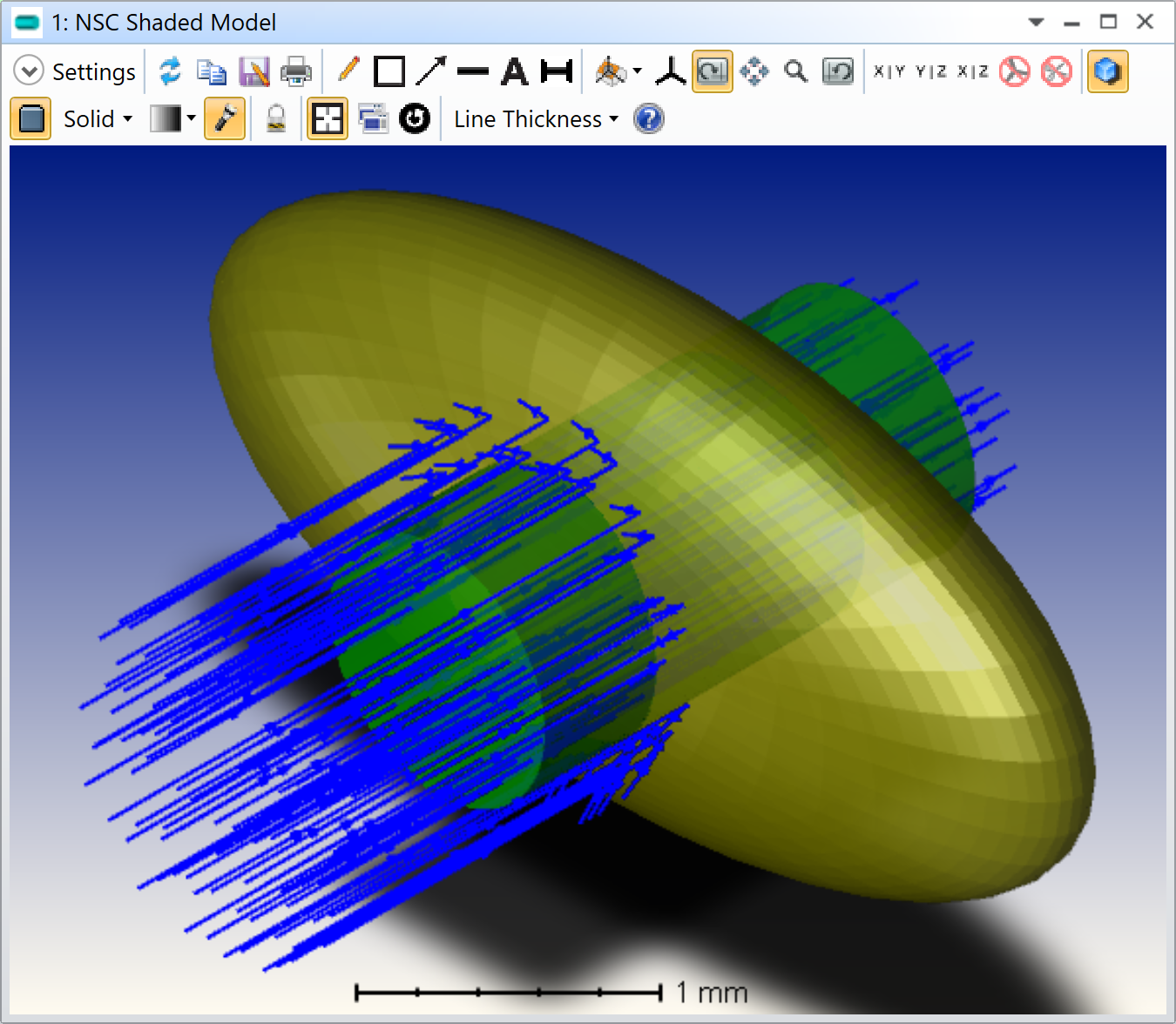
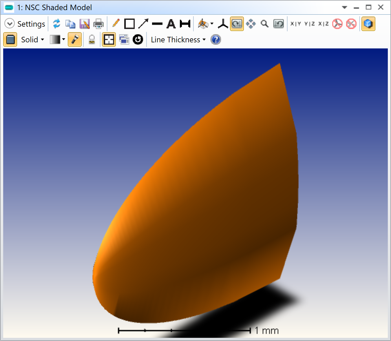
Here is an example (I’m using the Wikipedia naming convention) with a = 0.2, b = 1.0, and c = 2.0.

Ellipsoid rendering. a = 0.2, b = 1.0, and c = 2.0

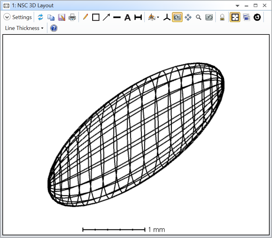
The rendering is done with triangles, but the ray tracing uses the actual ellipsoid equation F(x, y, z) given in the Wikipedia article.

The parameters are a, b, and c, as well as the number of triangles (for rendering only!) in the form of a number of samples for theta and phi (still according to Wikipedia naming convention). Please only use even number of samples and greater than four. Lastly, there’s a flag to toggle between a shell and a volume.

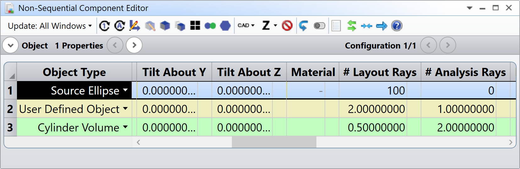
Because I couldn’t reproduce this ellipsoid with native objects, I just did a simple comparison with a Sphere object. I’m attaching my file so you can have the DLL and the comparison.

Ellipsoid comparison with a Sphere object

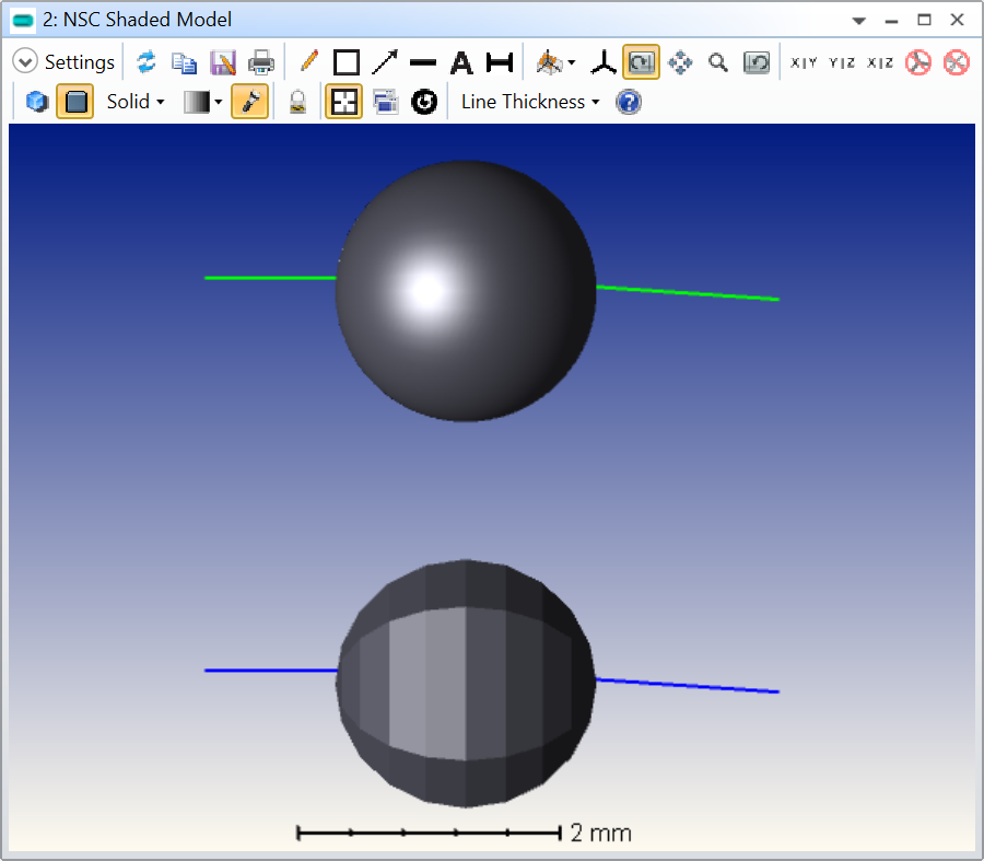
I was also using the Analyze..Single Ray Trace tool to make sure both behave in the same way, and it seems alright. I don’t know when you would change it to actual ellipsoid but I’ll work on it in the future. Its just that I don’t know when I’ll be able to work on this again so I wanted to share it :)

Take care,


David


5 replies

Userlevel 3

Very nice and I think we will use it in the (near) future for our simulations of more complex eye-models @Luc.van Vught just out of curiosity, how did you model the ellipsoid retina for our earlier non-sequential ray-tracing simulations?

Userlevel 2

This looks like a promising object indeed! Until now, I used STL objects to create ellipsoids in non-sequential mode. For instance, the objects used in this example. This DLL seems way more straight forward than creating vertices for an ellipsoid, converting them into a STL object and then loading that object.


To use the DLL for the retina, we might however have to look into adjusting the DLL to have a maximal polar angle / theta up to which the surface is drawn so we can have an opening at the front

Userlevel 7
Badge +2

Hi @jwbeenakker and @Luc.van Vught,


Good to see you here again. A few things for you:

  1. I’m not sure it is the best solution (but it is more intuitive I think) as it might be possible to use the biconic surface object, although I did not manage
  2. The DLL can be improved as you both know I’m not a software engineer!
  3. To create an opening in an object, consider using the nesting rule

https://support.zemax.com/hc/en-us/articles/1500005487401-Improving-non-sequential-ray-tracing-speeds-with-nested-and-Boolean-objects

Let me elaborate on the last point below. We are often tempted to make an exact replica of an object we want to simulate. However, it is often not the most efficient approach in terms of the speed of the raytracing. If you want to make a circular hole in the ellipsoid volume, here is what I suggest. Overlay a Cylinder Volume at the location of the hole and make sure the Cylinder Volume comes after the user-defined ellipsoid in the non-sequential component editor. When two objects overlap, OpticStudio resolves the ambiguity at their intersection by using the properties of the object that has a greater row number. Have a look at this reflective ellipsoid and how I made a hole in it using the Cylinder Volume:

Nesting rule: when two objects overlap, OpticStudio uses the object properties that are further down the NCE at their intersection.
Here you see that the rays outside the Cylinder Volume (green) get reflected by the ellipsoid. However, the rays traveling inside the Cylinder Volume simply ignore the ellipsoid.

Let me know if that makes sense.

PS: I’ve added the reflective flag to turn the ellispoid reflective or refractive. I’m attaching the new archive here as well.

Take care,


David

Userlevel 7
Badge +2

Just so people now what my problem is with the Biconic Surface Object. Using the formulas in the Help File, I have to fiddle with the Maximum X/Y Aperture column otherwise the shape isn’t drawn. For the shortest axis, I can’t set the Maximum X Aperture to 0.2, all I can do is set it to 0.199999999.

This somehow works, but I find it a bit hacky. Also, one needs two Biconic Surface Object, and I don’t know what happens at the contact point if the aperture is not exactly 0.2.

Take care,


David

Userlevel 7
Badge +3

That sounds like a bug. I’d get support to have a look at what’s happening at that specific value.

Reply