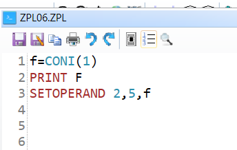
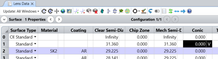
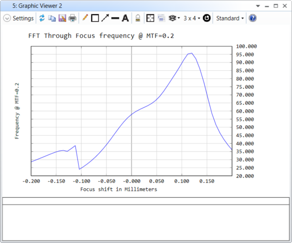
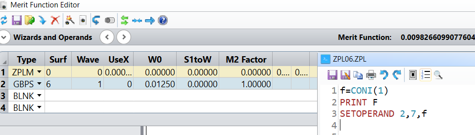
ZPLM tricks that you may don't know, but can be incredibly useful

  • 16 March 2023
  • 7 replies
  • 788 views

Userlevel 4
Badge +2

I will share examples of using ZPLM as a workaround to solve some problems that I see/ you may experience in my daily support 😀.  


7 replies

Userlevel 4
Badge +2

Example1 : 

Through focus spot diagram/Through focus MTF is the handy tool that can be used in imaging system analysis to quickly assess the performance of an imaging system as the image plane moves back and forth. MTF (Modulation Transfer Function) is a measure of the ability of an imaging system to transfer contrast at different spatial frequencies from the object to the image, and it is often used as a measure of system resolution. The lower the MTF, the less resolution the system can obtain at specific frequencies. In other words, if a lower MTF value is used as the limitation of human perception of sharpness, the corresponding frequency can be calculated when the image plane is moved at that specific MTF value. In the example below, MTF=0.2 is the threshold metric used for the evaluation.

Two macros are defined: 

  • ZPL06.ZPL
  • Through Focus Frequency.ZPL 

ZPL06.zpl is a macro that can be added to the Merit function editor as ZPLM. The purpose of this macro is to transfer a (dummy)parameter, specifically frequency, from LDE into the input parameter for an optimization operand. The parameter is further optimized in the second macro.

Example of using Double Gauss 28 degree field.zmx file: 

  1. Remove all variables through Optimize> Remove All Variables 
  2. Insert new surface before surface1 
  3. Set Conic of surface1 as variable 

Run the second macro: 


Userlevel 4
Badge +2

Example 2: 

Question and workaround: How can we evaluate the results of the paraxial Gaussian analysis of an optical system and obtain a 1-D curve of beam size vs M square at the image surface? The beam size can be evaluated by using the operand GBPS, but the built-in 1D universal plot cannot make M square an independent X value. One solution is to use ZPLM to change the M square input for GBPS and take advantage of the universal plot at the same time.

Example: In the attached file, ZPL06.ZPL can change the input parameter 7 (M square) for GBPS for MFE operand2. ZPLM is added before GBPS, and the weight for GBPS is set to 1 to make the reported merit function value equal to the GBPS value. With these settings, the analysis window shows the paraxial beam width vs M square.


Userlevel 5
Badge +3

Example3:

We need to limit the lens size for certain materials. When it comes to hammer optimization, we could not know the material in advance. So, we have to add a constrain to the semi diameter based on unknown material type.

Solution:

The glass type of a certain surface is read by the pass value PVHX.

Then it’s checked by the list we create and find the corresponding size limitation and get the limit output by

OPTRETURN.

The sample file is attached for your reference.

Userlevel 4
Badge +2

Example 4: 

Question: Determine the corresponding focus shift positions for the maximum MTF value from through-focus MTF analysis, for both tangential and sagittal directions. Extract these positions/MTF values in the merit function operand format to be added in MFE.

Solution: There are no built-in operands available to extract the value. However, you can create a user-defined ZPLM operand. First, create a normal macro code to report and print the values of interest. To extract values from the text report of an FFT through Focus MTF analysis window, you need to first open the analysis window and switch to the TEXT tab.

  1. Open the "FFT Through Focus MTF" analysis window. I’m going to extract data from this window, which is window number 4. Switch to Text tab


  2. Refer to the attached max_MTF_TTF_shift.ZPL, copy and paste in folder: C:\…\Documents\Zemax\Macros
  3. Run the macro to show the plot as below:


  4. Modify the macro slightly so that it can be used by ZPLM (attached ZPL08.ZPL). The following differences apply to the two macros:
    1. For ZPLM, window number is accepted as HX.
    2. For ZPLM, count of fields is accepted as HY. (0/ non-zero)


Userlevel 4
Badge +2

Example5: 

Question: POPD operands use different Initial beam/ Fiber Data settings in POP analysis setting window, how to make my POPDs use different POP setting window configurations.

There are three different CFG paths. First, I will describe the differences between the CFG files.

1. The CFG file with the same name as the file path
2. The CFG file in the ZEMAX data path (OpticStudio.CFG)
3. The POP CFG file in the ZEMAX data path (POP.CFG)

It's important to note that MODIFYSETTINGS can modify the contents of paths 1 and 3, but not path 2. 

The POP analysis window uses the configuration file in path 3, while the POPD operation in the MF uses the configuration file in path 2.

To modify the OpticStudio.cfg in the Zemax data path for the following POPD operand, we need to seek help from ZPLM, which is a user-defined merit operand. Within the merit operand, we can copy the required cfg file that has already been saved/modified and paste it as the configuration file that POPD will use.

Userlevel 3
Badge +1


Userlevel 4
Badge +2

Example 6: 

My colleague shared a link above that shows how to obtain the percentage of rays through in Analyze > Rays & Spots > Footprint Diagram Text tab. You can input the percentage value as an operand through ZPLM.

Reply