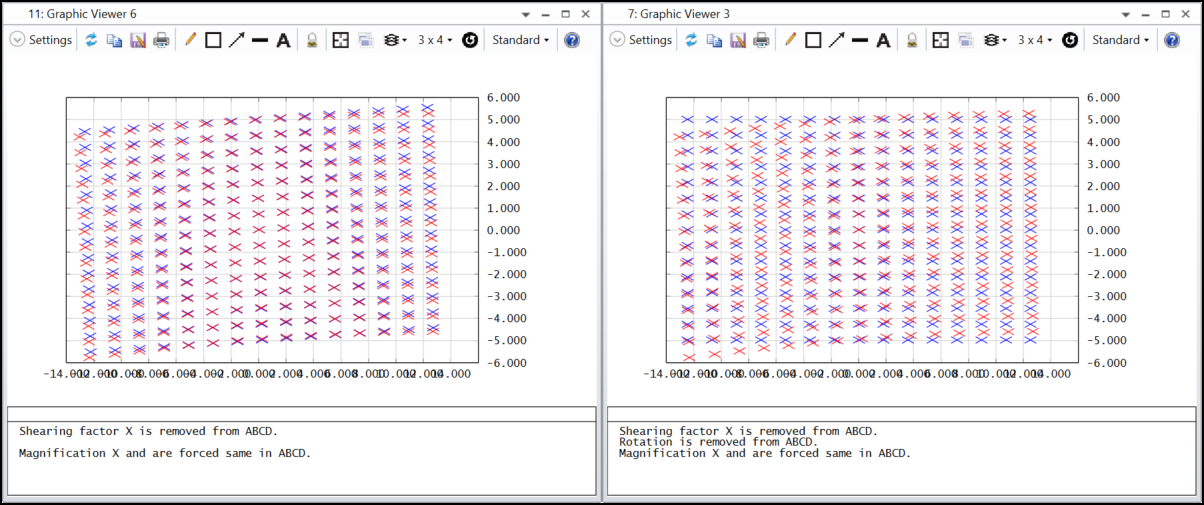
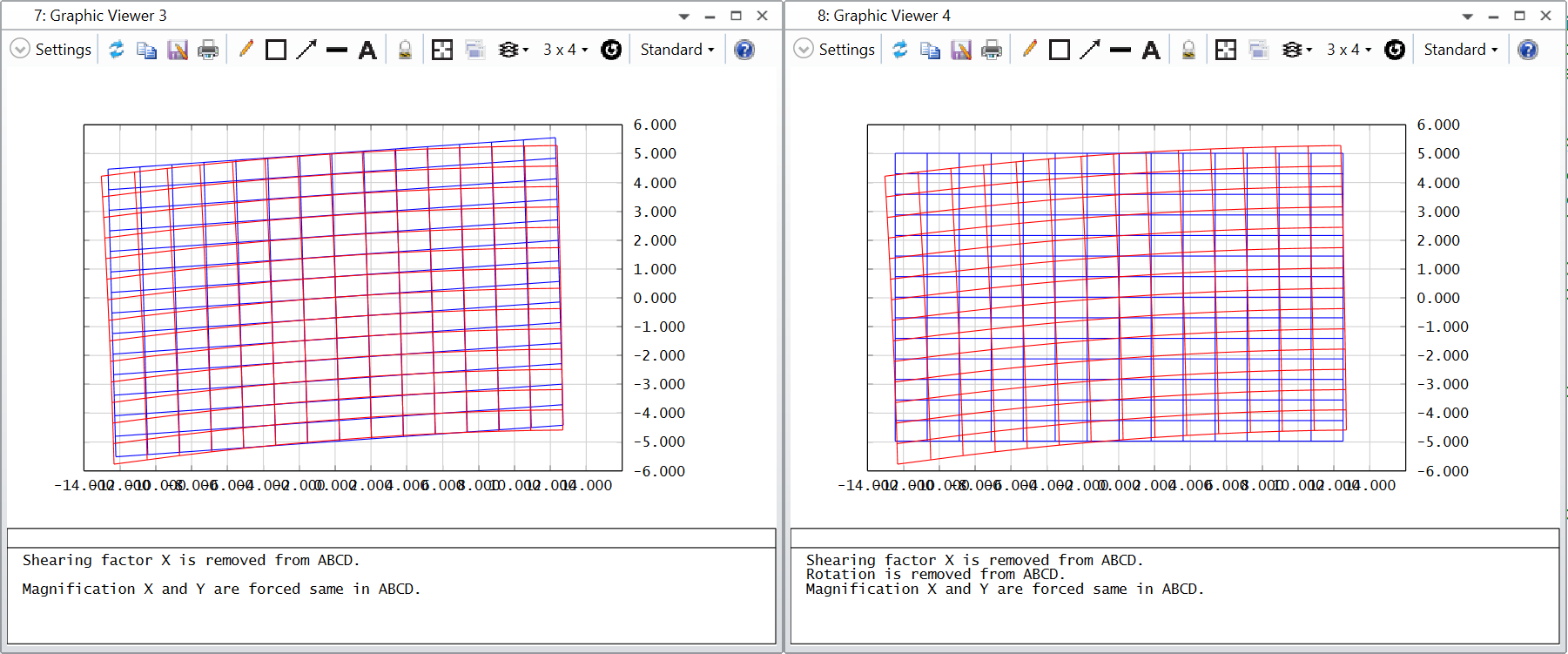
This code calculates grid distortion based on centroid.
- The advantage is it works for systems where the chief ray cannot reach image surface. Note that, although chief ray doesn't need to reach image surface, there should still be some rays reaching the image surface. This only works when the field type is either Angle or Object Height.
- Another useful points of this tool is it shows data on image coordinate, not object coordinate as in the native Grid Distortion analysis.
In the generated layout, you can see red and blue marks.
- Red marks are the centroid position of each sampled field.
- Blue marks are the 'reference' that serves as definition of 'no distortion'.
Note Red marks are the ray-tracing result of your system and cannot be changed. However, the blue marks is defined by ABCD matrix, which can be user-defined. In other words, there is no a standard of 'no distortion'.
The macro will automatically find a reasonable ABCD matrix just like the native Grid Distortion, but you can definitely change it. You can scale the ABCD matrix, or even define yours. ABCD matrix simply defines a linear transformation relationship between object plane and image plane.
Caution!
This macro is not comprehensively tested and is mainly showing a demo to users. Any question could be feedback to michael.cheng@zemax.com, but the fix is not promised to be soon.
Tip: This macro can potentially be used when ray-aiming doesn't work. In case the ray-aiming doesn't work, we can use this tool as below.
(1) make sure all surface has adequate aperture set
(2) turn off ray-aiming
(3) set STOP to first surface of the system
(4) set system aperture to Float by STOP Size
(5) enlarge the STOP size so that beams from all fields can fulfil the whole system.


