What is the difference between the operands NSRA 12 and 13? The manual says one is Phase of and the other one is Phase at.
Can you tell me whats the difference?

What is the difference between the operands NSRA 12 and 13? The manual says one is Phase of and the other one is Phase at.
Can you tell me whats the difference?
Best answer by MichaelH
Hi Bozkov,
tl;dr
Data 13 is very close to the optical path length and 99% of the time you’d be using this and ignoring Data 12
details
Data 12 (phase_of): additional phase added by a special surface/object in non-sequential mode (can use on any Object)Data 13 (phase_at): optical path length (OPL) referenced to the center of the pixel including additional phase coming from Data 12 (can only be used on a Detector object)In sequential mode, you can add any amount of arbitrary phase at any surface and this is translated into additional “bending” at that surface. In non-sequential mode, rays for the most part only know how to “bend” according to Snell’s Law. There are a handful of Objects such as the Binary 1, Binary 2 and Binary 2A which impart additional phase to the ray and cause the ray to bend more and Data 12 reflects this additional phase.
If the ray hits directly in the middle of the pixel on the Detector, then Data 13 is exactly equal to the OPL.
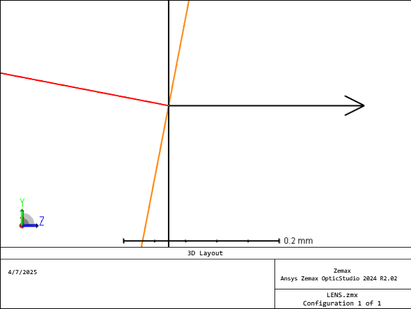
The OPL takes into account:
If the ray doesn’t hit the middle of the pixel, then Data 13 will also take into account the plane wave offset from the wavefront (surface perpendicular to the ray; orange below) and the pixel’s center (arrow to the right):
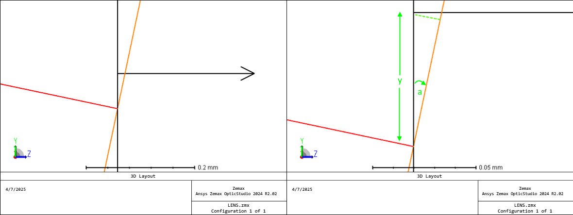
This offset (dashed green line) is simply the shortest path from the pixel center to the wavefront, namely sin(a) * y * 2 *pi / wllu (where wllu is the wavelength in lens units). The reason why this offset is needed is a pixel on a Detector acts as a finite binned well but all coherent calculations are corrected to occur at the middle of the pixel (common reference). This way, the destructive and constructive nature of the coherent light can be calculated correctly.
Enter your E-mail address. We'll send you an e-mail with instructions to reset your password.
Do not provide any information or data that is restricted by applicable law, including by the People’s Republic of China’s Cybersecurity and Data Security Laws ( e.g., Important Data, National Core Data, etc.).
不要提供任何受适用法律,包括中华人民共和国的网络安全和数据安全法限制的信息或数据(如重要数据、国家核心数据等)。
