Incorrect datagrid.MinY for Geometric Image Analysis
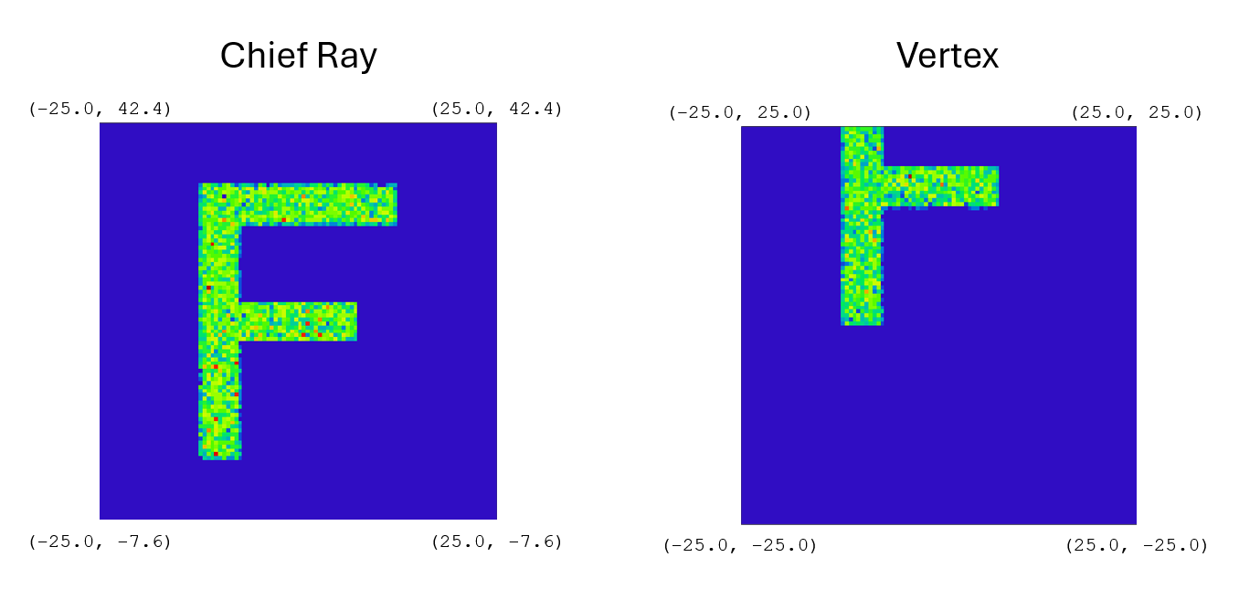
We recently implemented the Geometric Image Analysis in ZOSPy 1.30. While doing so, we noticed that IAR_DataGrid.MinY does not return the lower bound of the y-axis for the output (at least when compared to the output in OpticStudio itself). It seems to be returning either the upper bound or the abolute value. E.g., when the analysis is centered at (0,0), the x- an y-axes in OpticStudio start at -25 while the API returns -25 for MinX and 25 for MinY.
Could you elaborate on what MinY (and to an extend MinX) correspond to. So far, we thought the datagrids and their axes follow the normal matrix conventions, which was the case for all analyses we implemented and used. Is this not the case for Geometric Image Analysis, or is there an error in the API?
Page 1 / 1
Is there any update on this? I would like to know that MinY actually returns
It might be worth tagging @MichaelH for such an issue.
Take care,
David
This is definitely a bug for the ZOSAPI.Analysis.AnalysisIDM.GeometricImageAnalysis feature, but maybe not for the obvious reason.
What MinX and MinY are supposed to give is the physical coordinate of the “bottom left pixel” of the DataGrid (remembering that this is actually grid.ValuesV0, 0] and you’ll need to perform a flipud to get it in the same orientation as OpticStudio). So, if you are using a WavefrontMap, MinX=-1 and MinY=-1 because of the normalized pupil but if you’re using FftPsf, then this value would be in microns. To get the width and right most pixel value, you could use something like:
width = grid.Dx * grid.Nx right = grid.MinX + width
where Dx is the delta between pixels in the x direction and Nx is the number of pixels in the x direction.
The IAR_ interface reads the ZDA file structure and populates the fields accordingly (there is no additional calculations performed in the ZOS-API...it simply “reads” the data being passed out of the core code). Comparing the Text Tab for both the FFT PSF and the Geometric Image Analysis, it looks like the core code for FFT PSF actually calculates things like Dx and Reference Coordinate (to get calculate MinX). However, for Geometric Image Analysis, the core code doesn’t pass back a corresponding value for the Reference Coordinate. The Reference Coordinate is needed to get the physical MinX and MinY values. The Reference Coordinate value is determined by the IAS_GeometricImageAnalysis.Reference property and can be:
ChiefRay (REAX/REAY)
Vertex (GLCX/GLCY)
Primary Chief (REAX/REAY)
Centroid (CENX/CENY)
You can get the values for the Reference Coordinate by using the MFE operands in parenthesis. The Nx and Dx values for GeometricImageAnalysis are correct, so with the calculated Reference Coordinate, you can get the correct MinX and MinY values.
Since the Geometric Image Analysis doesn’t provide a Reference Coordinate in the ZDA, I would file a bug report with the ACE team. The MinX and MinY values should be set to NaN so improper conclusions are not drawn by the engineer.
Thank you for the elaborate response as well as for filing a bug report! I will try to find a way to correct this in ZOSPy for now. Just to be sure: the only way to get any of REAX, REAY, GLCX, GLCY, CENX, CENY is through the MFE correct? That is by itself easy to implement, but I would rather not alter large merit functions that people are working with while running the analysis. I think recalculating a large merit function for the sake of running the GeometricImageAnalysis is not ideal. This leaves me with two other options that I can think of:
Temporarily save the current merit function, clear the MFE, add e.g. REAX, REAY , calculate, reload the original merit function.
Obtain e.g. REAX, REAY through another analysis.
I think option 2 would have my preference as we do not alter the MFE that way, but then I need an analysis that provides REAX, REAY in its output. Is there such an analysis @MichaelH? So far I cannot find one.
@Luc.van Vught
I’m not sure it’ll help but you can evaluate single Merit function operands outside the MFE with the method GetOperandValue (of the IMeritFunctionEditor interface).
It doesn’t work for operands which rely on other operands, but should be ok for REAX and REAY.
Also, I think @MichaelH is suggesting that you file a bug report in his original message.
Take care,
David
@David.Nguyen thank you for the tip! I started with an implementation here.
@MichaelH follow up question: when wavelength is set to "All", reference to anything but "PrimaryChief" and there are multiple wavelengths, how does OpticStudio determine the Reference Coordinate? Does is calculate one for each wavelength and then average them? I cannot find this in the manual.