Hello Everyone,


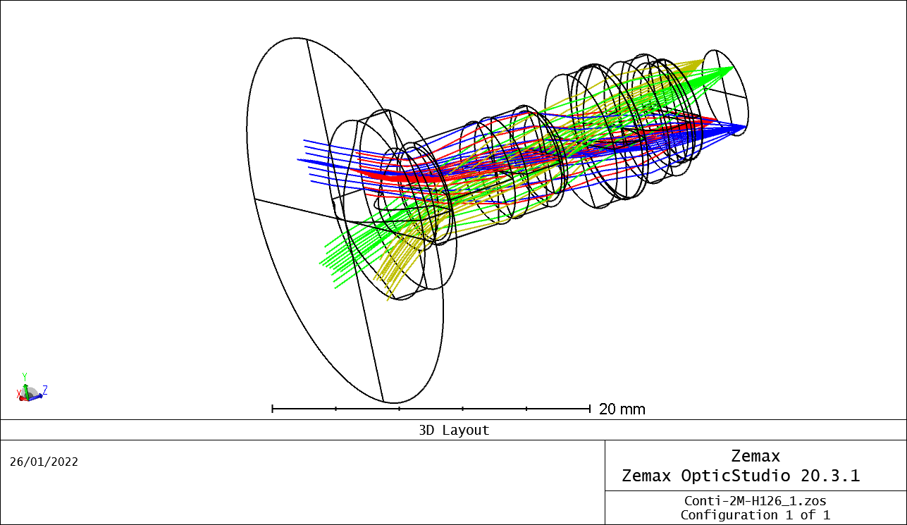
I have the model for an automotive camera lens. I also have the samples of the lenses to perform measurements.

Here is what I would like to do with the model (I am an absolute novice in programming):

I would like to specify points in the objects space (varying the object distance and the object height position) and would I would like to extract the Huygen’s MTF and PSF for all these points. I would also like to know the position of the image (of the point) on the imager.

So far, I have understood that I can vary the object height points in Python, I am however, not sure how I can vary the object distance!

I tried to use the example code for “Retrieve Data from FFT MTF” and made some modifications to extract the MTF information for my lens file. It seems to work for the FOV points (by object height) already specified in the lens model and a constant object distance but I would like to do the same for a list of points in the object space and would be nice if it can be automated.

My questions are:

Is it possible to vary the object distance in a similar fashion as it is for the object points?

How can I get the the position where the chief ray strikes the imager for a certain point on the object space?

The idea is to extract raw data and not plots so that it can be compared with measurement data.

Any lead in this area would be highly appreciated.


With best regards,

Amit


Hello Amit,


Varying the object distance generally means changing a surface thickness in your lens data editor. In Python, this can be done with:

TheSystem.LDE.GetSurfaceAt(1).Thickness = 10.0

Change the nunber one with the surface number containing the object distance (possibly the last glass element). Then, you can set any value for the object distance you like, I’ve put 10.0 in my example, but you go have it iterate through a for-loop.

To track the position of the chief ray across fields, I’d recommend using a Merit Function operand such as the real ray height: REAX, and REAY. A Merit Function operand can be quickly evaluated in the ZOS-API as shown below:

surface = 12

wave_number = 1

Hx = 0.5

Hy = 0.5

TheSystem.MFE.GetOperandValue(ZOSAPI.Editors.MFE.MeritOperandType.REAX, surface, wave_number, Hx, Hy, 0, 0, 0, 0)

In my example, you can change the surface number to wherever your image is and adjust the wave number as necessary. Then, you can choose a field height with the values Hx, and Hy (I’m assuming you know what this means otherwise let me know). The last line will evaluate the operand REAX with the corresponding settings. I have not put Px, and Py since you are interested in the chief ray (Px = 0.0 | Py = 0.0).

Let me know if that makes sense.

Take care,


David


Hello David,

Thank you for the response. 

Varying the object distance generally means changing a surface thickness in your lens data editor. In Python, this can be done with:

TheSystem.LDE.GetSurfaceAt(1).Thickness = 10.0

Change the nunber one with the surface number containing the object distance (possibly the last glass element). Then, you can set any value for the object distance you like, I’ve put 10.0 in my example, but you go have it iterate through a for-loop.


I always assumed that the surfaces (in Python) are numbered according to the row numbers in the LDE and hence was unsure if I could use thickness of “surface 0” which defines my object thickness (distance) in the LDE. If I change the thickness of the last element, will it not just change the distance between the second last and the last element? For instance in my lens, surface 0 is the object, surface 16 is the image and the rest are stop and lens surfaces.


Edit: I found out by using the “Surface0” I am able to modify the object distance. :)

To track the position of the chief ray across fields, I’d recommend using a Merit Function operand such as the real ray height: REAX, and REAY. A Merit Function operand can be quickly evaluated in the ZOS-API as shown below:

surface = 12 wave_number = 1 Hx = 0.5 Hy = 0.5 TheSystem.MFE.GetOperandValue(ZOSAPI.Editors.MFE.MeritOperandType.REAX, surface, wave_number, Hx, Hy, 0, 0, 0, 0)

In my example, you can change the surface number to wherever your image is and adjust the wave number as necessary. Then, you can choose a field height with the values Hx, and Hy (I’m assuming you know what this means otherwise let me know). The last line will evaluate the operand REAX with the corresponding settings. I have not put Px, and Py since you are interested in the chief ray (Px = 0.0 | Py = 0.0).


I am assuming Hx and Hy define the object position in the object space for a given object distance and can be changed in the field setting. If I am right, this would help me define a certain number of points in the object space by defining different values for Hx and Hy?

Is there a way to exchange code between Interactive and Standalone applications? Most of the sample codes are for standalone application but I would like to see the changes I make in the code being reflected in the OS environment so that its easier for me to verify my code.

Thank you once again for your response.


Amit


Hi Amit,


You are completely correct. Surface zero can be chosen as a valid surface. I had picked surface one randomly, just to show how to use the line of code. You could also do:

TheSystem.LDE.GetSurfaceAt(0).Thickness = 10.0

I misread your post and thought about image-distance as opposed to object distance.

You are correct again, Hx, and Hy define your object (or field in OpticStudio) position. Have a look at the Help File (F1) under Conventions and Definitions > Normalized Field Coordinates. Hx, and Hy are values between zero and one that describe the extent of your field (object) size. This is an excerpt from the Help File section:

Normalized field coordinates are used in both the OpticStudio program and documentation. There are two normalized field coordinates: Hx and Hy. Normalized field coordinates are convenient because useful field locations may be defined in a manner that does not change with the individual field definitions or field of view of the optical system. For example, the normalized field coordinate (0, 1) is always at the top of the field of view, whether the field points are defined as angles or heights, and regardless of the magnitude of the field coordinates.

Let me know if this makes sense.

Take care,


David


Hi David,


All of this makes sense now. Thank you for the quick response.

Could you please let me know if there is a way to modify the standalone sample code to use it for interactive session?


Amit


Hi Amit,


Sorry, I didn’t read your last question. I don’t know if there’s a way to modify a standalone application to make it into an interactive extension, but what you can do is create an interactive extension by pressing Programming..Python..Interactive Extension, and then copy the parts of the examples you are interested in below the line:

# Insert Code Here

If you look at Example 1 for example, you could simply copy the lines after the Load local variables bloc starting with:

# creates a new API directory

and up to:

#! >e01s09_py]

Don’t copy the very last part with del zos and zos = None, since zos is not defined in the boilerplate code of the interactive extension.

Let me know if this is clear.

Take care,


David


Works like a charm.

Thank a lot David.


Best regards,

Amit


Hi @David.Nguyen  ,


Just a quick few questions about something that is still confusing me:

  1. When i use the Hx and Hy in combination with the object distance what i am essentially defining is the overall object size. Eg, if Hx and Hy are both defined as 0.5 m and the object distance is 100 m, does ZEMAX consider this point in the object space as a separate point source? I ask because I see in the layout that the object at this position is not a point source. Or does ZEMAX take the overall specifications of the FOV and defines that as a whole scene?
  2. Is there a way to extract the RX and RY values that we discussed in our last conversation through the OS GUI? I ask this because I would like to verify the values for a standard lens so that I can ensure that my code is extracting the correct values. As far as I have reached I can use the single ray trace option to extract these values. Is that right?

Please let me know :)


Thanks a lot,

Amit


Hi Amit,


Here are my answers:

  1. Technically, when you define Hx and Hy, you define the starting coordinates of a ray in the Object plane. And remember, Hx and Hy don’t have units. There are just numbers between zero and one. What gives the units to the starting coordinates is the most extreme field point in your system (Setup..System Explorer..Fields). For example, if your field definition is Object Height, and the largest field you have is 5.0 m along Y. Then setting Hy to 1 means the ray will start at 5.0 m on the Y axis. If Hy = 0.5 then the ray starts at 2.5 m. Does that make sense? The operand REAY, which uses Hx and Hy traces a single ray through the system, it isn’t a source.
  2. I don’t remember talking about RX and RY, could you clarify what you are referring to? But, you can absolutely use the single ray trace to keep track of a ray defined by Hx and Hy

I hope I understood the quation correctly, but don’t hesitate to tell me otherwise. Take care,


David


Hi David,


thanks for the quick response. Unfortunately, my hurry to write the question before I left for a meeting made me make some mistakes. Please accept my apologies for that.

  1. That makes sense.  Hx and Hy are normalised which is why they do not have units. So if I understand you correctly, with the Hx and Hy I define, on an abstract level, “a scene”. The scene is a 2D plane at a specific distance (specified by the “thickness” parameter from the object surface to the first lens surface). I can define multiple points on this scene from which the rays are traced. Eg. Hx and Hy=1 will define the maximum limits of the scene and a value of Hx and Hy between 0 and 1 will define additional points in this scene.
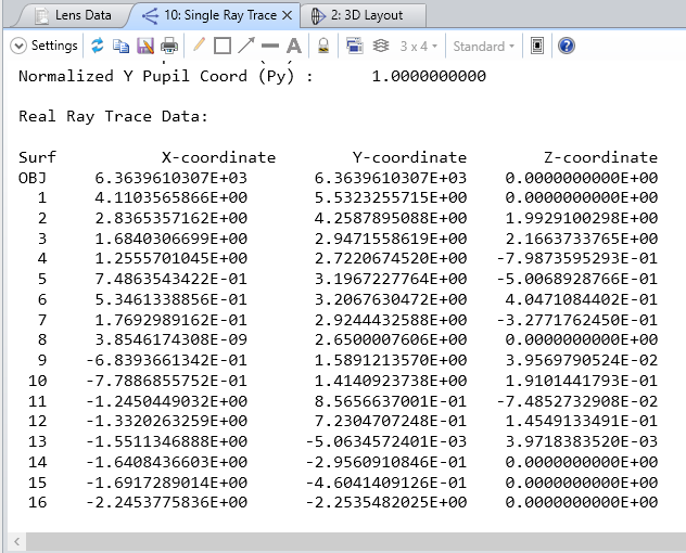
  2. Again, my apologies, I wanted to mean the REAX and REAY. Now, if I want to trace the marginal ray, through one random point in the “scene” eg, Hx and Hy=0.5 to the image surface, then I run a single ray trace in the GUI and enter the Hx and Hy and the suitable surface number in the settings accordingly. With this, in the results, when I look at the X, Y coordinates these are the values of coordinates where the marginal ray hits the image surface. Am I understanding that right? What significance does the pupil coordinates (px and Py) have here? If I assume correctly, I need to set the pupil coordinates to 1 to extract the marginal ray information. Is that correct?
    Single ray trace window


I hope I was able to explain it well enough.


Best regards,

Amit


Hi Amit,


No problem, let me try to complete my answers then.

  1. This is not typically how I would describe the role of Hx and Hy, but if that works for you it is probably fine. From what you wrote I think you understood the concept but let me make some clarifications in your point 2 below.
  2. So far, we’ve kept Px and Py at zero because you were interested in the chief ray. In OpticStudio, a ray is completely defined by the values Hx, Hy, Px, and Py. Px and Py are the pupil coordinates and by definition, the chief ray passes through the center of the pupil (Px and Py are zero). If you set Px or Py to one, you are indeed tracing a marginal ray that started from Hx and Hy. For the rest, you are completely correect indeed.

Take care,


David


Reply