Hi Christian,
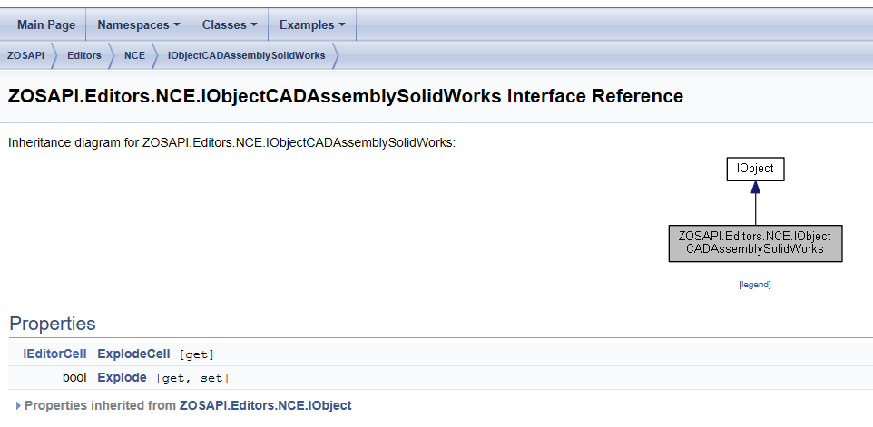
I have taken a look at our documentation, and it looks like the Explode tool is not yet implemented in the API. Right now, the only property related to a CAD assembly explosion is found in the ObjectData for a CAD Assembly object:
The syntax for using this would look like the following:
Obj1 = TheNCE.GetObjectAt(1);
Obj1_Type = Obj1.GetObjectTypeSettings(ZOSAPI.Editors.NCE.ObjectType.CADAssemblySolidWorks); % create CAD object type
Obj1_Type.FileName1 = 'Assem1.SLDASM'; % set CAD file to be used (file must be in valid directory)
Obj1.ChangeType(Obj1_Type); % Set Object 1 as the previously specified CAD file
Obj1.ObjectData.Explode = true;
Unfortunately, it looks like all this does is make Explode? = 1 in the Non-Sequential Component Editor. As we know from the Help System file on the topic, this cell is used by OpticStudio as a reference, and does not actually create the necessary part files. I have added a feature request in your name asking for this ability to be added to the API. In the meantime, you could try importing the consituent part files of the assembly as STEP files. This is essentially what the Explode tool is doing! That should allow you to perform the same path analysis you are looking for.
Regarding your question about the help system - have you found our article on the ZOS-API structure? That, in conjunction with the videos, helps to clarify the different variable types you will find in the API. In addition to that, I have made a few posts which detail my own methods for navigating the syntax guide and troubleshooting code. Here are two examples:
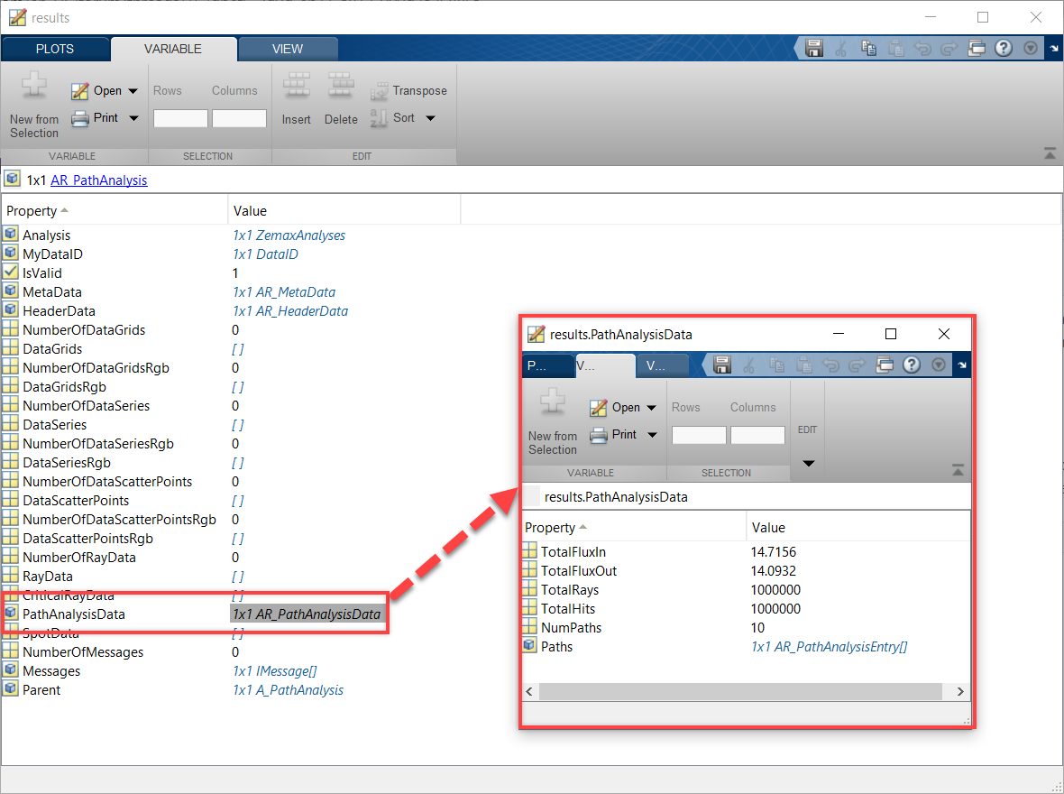
Finally, with respect to the Path Analysis window in the API, the results are actually stored in a different manner than most other analyses. If we inspect the object created by the line results = pathAnalysis.GetResults()
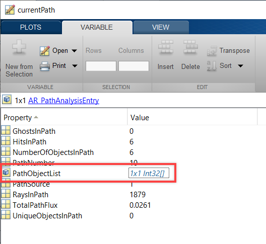
then we find it does not have any data grids/series, but instead has a PathAnalysisData object. This holds the ray data for a particular path:
A colleague of mine wrote some code for analyzing flux with the Path Analysis tool. It is in C# but the API-specific syntax should be very similar to what you will use in Python. Here is the code:
Console.WriteLine('Path analysis flux results:');
ZOSAPI.Analysis.Data.IAR_ Rays = RayPath.GetResults();
ZOSAPI.Analysis.Data.IAR_PathAnalysisData allPaths = Rays.PathAnalysisData as ZOSAPI.Analysis.Data.IAR_PathAnalysisData;
for (var path = 0; path <= Rays.PathAnalysisData.NumPaths - 1; path++)
{
ZOSAPI.Analysis.Data.IAR_PathAnalysisEntry curPath = allPaths.Paths[path] as ZOSAPI.Analysis.Data.IAR_PathAnalysisEntry;
double flux = curPath.TotalPathFlux;
Console.WriteLine('\tFlux in path {0}: {1}', path + 1, flux);
}
Console.WriteLine('\nPress any key to continue...');
Console.ReadKey();
Essentially the code is checking for the number of paths. Then, for reach path, the code is accessing that PathAnalysisData object and extracting the flux. Would something like this work for you?
Let me know if you have any questions about this!
Best,
Allie
Hi, Allie,
thanks for your answer.
I should be able to unpack my CAD file for my project. The thought came to my mind whether this would be possible with a macro and whether I could do this with my program.
I mean to have read that unfortunately this is not possible, but it would be a very big performance gain for further functions, if this is possible.
Most of the articles about the ZOS-API structure I already knew before and are understandable for me with the 'outer' objects and commands, but when it goes deeper into the program structure I have problems to find the right commands or to recognize how the structure is structured.
The file path (ZemaxUI.ZOSAPI.Analysis.RayTracing.AR_PathAnalysis) of your described object results = pathAnalysis.GetResults() I cannot find in the help.
I understand the basic idea of the code, but because of the other language, I do not understand the syntax exactly, so I cannot apply it myself.
With kind regards,
Christian
Translated with www.DeepL.com/Translator (free version)
Hi Christian,
With respect to unpacking the CAD file - could you try to manually add all the parts as STEP files and position them using the Ref Object column in the Non-Sequential Component Editor? This would allow you to position all STEP files with respect to the assembly's global origin. That would have the same effect as the Explode tool. I can help you with this setup as well, if needed! In that case, maybe we can switch to a MyZemax case to begin a private conversation about the file.
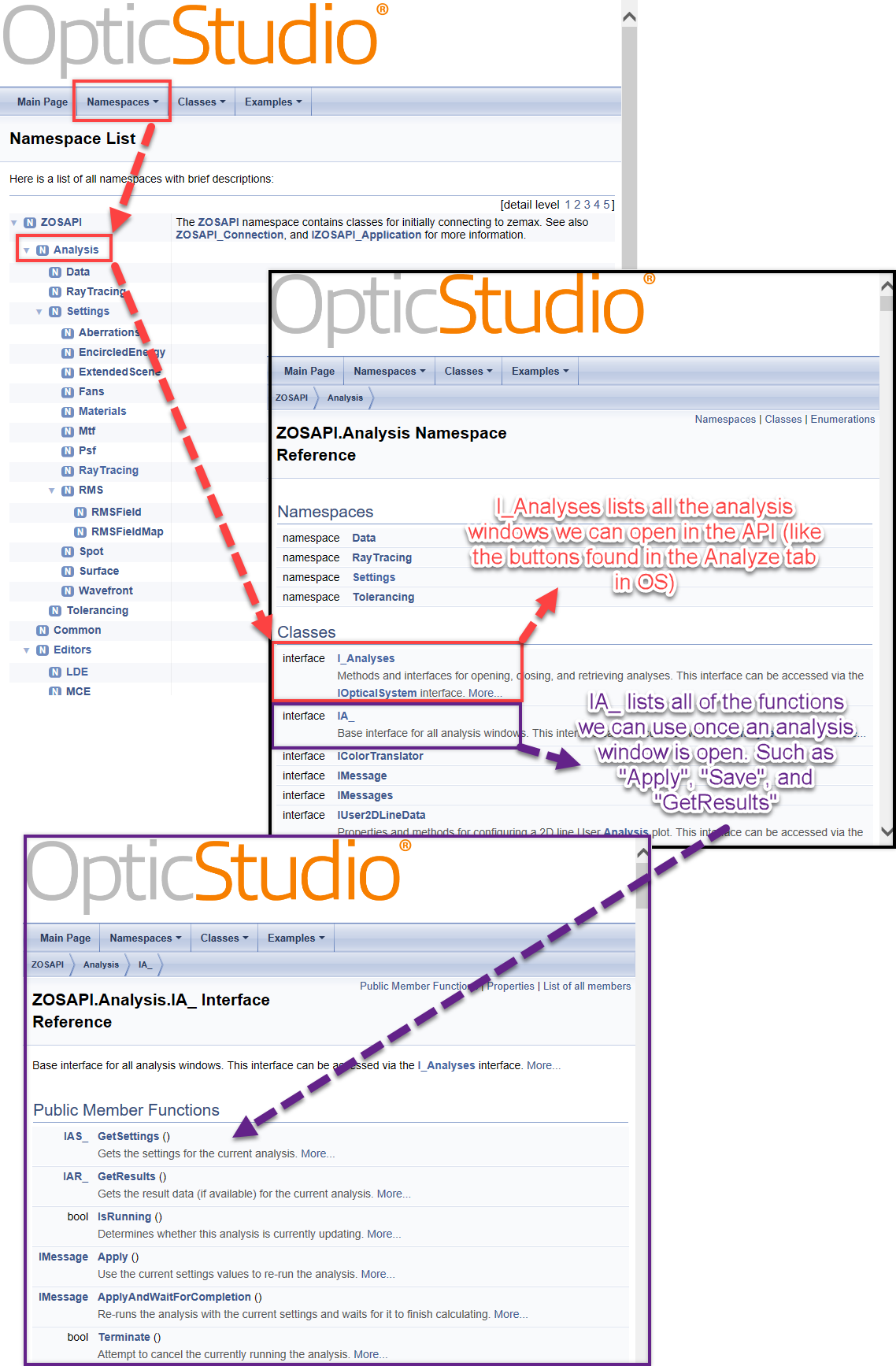
I think the best recommendation I can make for you regarding the help would be utilize the Namespace list in the syntax guide and to utilize the debugging tools you have in your distribution of Python. Regarding the former, the Namespace list has a very similar 'flow' to what you would expect when using the UI of OpticStudio. For example, if I want to access an analysis and run it, I would follow this journey:
In general, when you are looking for a command in the API, think about where it would be found in the UI. If you want to change something in the Non-Sequential Component Editor, begin by looking in the Editors Namespace.
Regarding the Python's debugging tools, this will depend on what distribution you're using. In general, you should be able to open an object and see what properties are 'housed' therein within your program. You can see I did that in my initial response to you when I accessed the results and the PathAnalysisData interafaces through Matlab. It may also help to get a better understanding of object-oriented programming in general. Here is a resource I found on that subject: https://realpython.com/python3-object-oriented-programming/.
Finally, if you have questions about properties or API capabilities, you should always feel free to post them here on the MyZemax forums. We have many users and Zemax staff who are knowledgeable in the API and can help you find a tool if you're unable to locate it in the syntax guide.
Best,
Allie
Hi, Allie,
manually insert the STEP files is not an option for me, because I plan to insert the finished CAD file directly. These often have more than 100 parts and if I want to create single STEP-files this means an immense amount of work.
I wonder why this feature is not implemented in the ZOS-API since it is already implemented in the GUI.
Since there are often other commands implemented in the macros I would at least have the hope if it would be possible to explode my file.
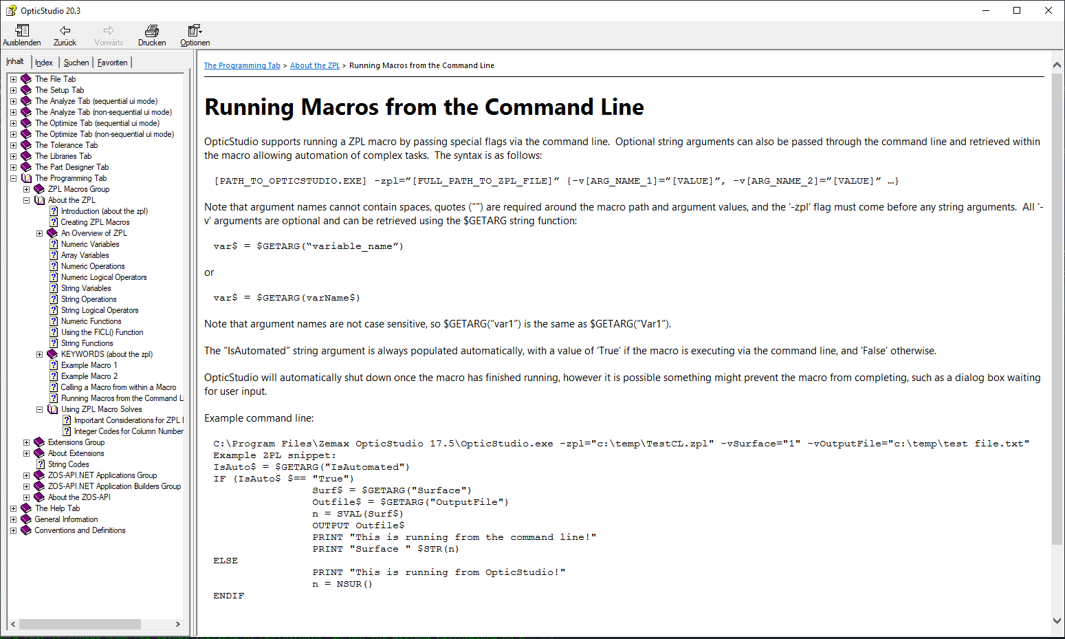
As I would also prefer to change my material via a macro I looked for possibilities to start this from my Python program and found 'Running Macros from the Command Line'.
Since I couldn't manage to start a macro with this I wanted to ask if there is anything else I have to consider.
The pictures concerning the procedure of the analysis helped me a lot, because before I didn't understand how the 'IA_', 'IAR_' is constructed.
But I did not understand why I get the following error with my code:
'TypeError: 'NoneType' object is not callable'
I have used your code as a template. How do I output the image of an analysis in ZOS-API?
Additionally I tried to look at my object structure like you did in Matlab. I am using Spyder 4.1.4 as IDE and when I try to use the 'Object Explorer' the following error message appears:
I hope I don't ask too many questions and thank you again for helping me.
With kind regards
Christian
Hi Christian,
I'm looking at the available macro commands, and I don't see a way to explode the assembly there either. For now, I would recommend saving a new version of your file in which you manually explode the part using the toolbar command. Then you can open that file in the API for further analysis.
Is there a reason you prefer to use a macro to change the material of an object? This can be done in the API through the INCERow interface. At this time, there is no direct way to run a macro in the API. I have found two workarounds, but they will take more time than simply adding the line in the API code itself. Here are my solutions:
- Create a ZPLM operand which performs the actions you are looking for. Add it to the Merit Function and run the Merit Function. Do note: This method is not recommended if you are applying changes to the file. Optimization operands themselves should not try to alter the lens file.
- Use the command line to run a macro. This can be done, but is a little tricky. When we run the macro through a command line, a separate instance of OpticStudio will be opened and the actions performed on that separate file. Additionally, you will probably have to change the working directory to get the command line to work in Python. At least, that is what must be done in Matlab. I have written code to make this happen and can send it here if you are still interested! Ultimately, though, I would recommend staying with API commands where available.
Regarding your code: the reason you are getting a NoneType error is because the Path Analysis tool does not have any Data Grids. Back in my first post, you can see that NumberOfDataGrids = 0 in the Path Analysis results interface. Instead, Path Analysis data is stored in an object titled PathAnalysisData
. Earlier, I provided you with some code in C# to extract the data into the API. I have translated it into Matlab. Here is the code:
pathAnalysis = TheSystem.Analyses.New_Analysis(ZOSAPI.Analysis.AnalysisIDM.PathAnalysis);
pathAnalysis.ApplyAndWaitForCompletion;
results = pathAnalysis.GetResults();
allPaths = results.PathAnalysisData;
totalPathNum = allPaths.NumPaths
for i = 1:totalPathNum
currentPath = allPaths.Paths(i);
flux = currentPath.TotalPathFlux;
objPath = int32(currentPath.PathObjectList);
end
For the most part, you should be able to translate this directly into PythonNET. The only changes you need to make are to the definition of the FOR loop, and to the line starting with objPath
. The PathObjectList is given as a 32-bit signed integer in the API:
In Matlab, the command int32 will translate it into an array or matrix. Here is the result for the last path:
I'm not sure how Python reads 32 bit signed integers, but I did find a reference that discusses this variable type and how it relates to numpy: https://numpy.org/doc/stable/user/basics.types.html.
Note: In general, what you tried to do is correct. Most analysis tools have either a Data Grid or Data Series. Path Analysis is pretty unique in that it has its own, new property.
Regarding that final point: I'm not sure what that error means. According to a Spyder developer: However, if objects can't be pickled (i.e. serialized in the kernel), there's nothing we can do about it to show them, sorry. I wonder if Spyder is unable to investigate the API objects? That would be weird to me as I can usually get more information about an object when using Python in Visual Studio. My colleague Julia has shown how she debugs Python code in this forum post. Are you able to try something similar in Spyder?
Also no worries about asking questions. That's what we're here for!
Best,
Allie
Hi, Allie,
Ok, then I won't be able to let my program automatically break it down into its individual parts.
The reason why I would prefer a macro here is a much shorter runtime for converting the materials and for other processes macros are already available internally. Since this is only possible in a detour, the first reason could be nullified, but I would like to test this myself.
I have also tried to call a macro directly via the command targets, but without success.
As described in the help I tried the following:
C:\\Program Files\\Zemax OpticStudio\\OpticStudio.exe' - zpl='C:\\Documents\\Zemax\Macros\\Material.ZPL' -vSurface='1' -vOutputFile= 'C:\\API\\16_1.zmx'
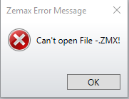
OpticStudio opened and I received the following error.
I also tried to use the file I want to edit on startup, OpticStudio opened with the correct file but did nothing afterwards.
'D:\\API\\Test16_0.zmx' - zpl='C:\\Documents\\Zemax\Macros\\Material.ZPL' -vObject='1' -vOutputFile='D:\\API\\Test16_1.zmx'
and
'C:\\Program Files\\Zemax OpticStudio\\OpticStudio.exe' - zpl='C:\\Documents\\Zemax\Macros\\Material.ZPL' -vInputFile='D:API\\Test16_0.zmx' -vOutputFile= 'D:\\API\\16_1.zmx'
I have also tried other variants and searched for them, but without success, and would be happy about an example.
Your MatLab code helped me a lot, I only had to adapt a few small things for Python.
Unfortunately I don't understand why it is not possible there. The 'Object Explorer' hasn't been around in Spyder for too long, so I hope that it will be improved.
Such a syntax help is also available in Spyder, but I haven't tested it with regard to API programming because I was afraid that it wouldn't work here. But I will test this tool now in the hope for better programming.
With kind regards
Christian
Hi Christian,
I'm glad my code worked for you .
If you'd like to test running the macro, here is what I came up with for running a macro from the API through the command line. In my example, the macro is being used to open a Shaded Model and save it as 'ShadedModel.JPG' in the path specified by the path name.
The macro is attached. It will accept two inputs: path name (path to the OS file) and file name (name of the OS file).
Again, my example is in Matlab but since you were able to translate the last example, I'm hoping this will be the same! To execute in Matlab, we have to change the directory to the OpticStudio Program Files. Then we use the system command to execute the operating system command line function. Here is the syntax:
% Change directory to the OS Program Files
% Use the OS.exe to run a macro
% The macro accepts: path name and file title
% The macro will open the file, open a Shaded Model, save it, then
% close the Shaded Model
cd 'C:\Program Files\Zemax OpticStudio 20.3.1\';
system('OpticStudio.exe -zpl='C:\Users\Alexandra.Culler\Desktop\Zemax\Macros\Test.zpl' -vFilePath='C:\Users\Alexandra.Culler\Desktop\WFH\TestFile' -vOutputFile='\Cooke 40 degree field.zmx'');
We see that “-zpl” is equal to the name of the macro I want to execute (path included). Then, “-vFilePath” is equal to the path holding my OS file. Finally, “-vOutputFile” is equal to the OS file we will be saving the image from. The result is a ShadedModel.JPG file in the path “C:\Users\Alexandra.Culler\Desktop\WFH\TestFile'” path. You can, of course, add more inputs, like an input to make a unique name for the Shaded Model if needed.
If you utilize this, you should note that the command line execution of the ZPL will open a new instance of OS in order to run the macro. You will need to make sure you are not already using the maximum number of instances before running this!
Since this opens a whole new file, I do not expect this to be faster than using the API-native commands. One example to perform the actions you're looking for would be:
TheSystem = TheApplication.PrimarySystem;
TheNCE = TheSystem.NCE;
obj1 = TheNCE.GetObjectAt(1);
obj1.Material = 'BK7';
It may be worthwhile to translate any macros you have into native API code (where possible). Though do let me know what you find with respect to your tests!
Have a great weekend!
Allie
Hi, Allie,
The MatLab code is mostly very similar to Python, so I usually only had to replace single commands.
I hope I can now complete my program with your help and thank you for your good and detailed help.
By your example I managed to call a macro using my Python program and could make first tests regarding the speed of my program.
By opening a new OpticStudio instance, opening the zmx file by the macro with subsequent saving and reloading in Python, I always need a certain amount of time.
When I run through my data, in which I want to filter and change things, I can achieve a speed gain, despite this time, with an unpacked CAD file.
For most small changes it makes sense to stay in one environment (ZOS-API), especially since you only have to get used to one environment.
For the systematic analysis of OpticStudio files it can be interesting to create an external program using an external programming language and let a macro do the analysis. In this way, the versatility of external languages and the speed of macros can be used.
I have another problem:
I would like to read the txt files I get from OpticStudio into Python. This would allow me to compare the results without having to open several OpticStudio files (what difference does a different coating of a component make).
Reading in Python is no problem, but processing the txt file causes me problems. If I want to split a line using the spaces or whitespace, I get a list with many strings, which are empty.
I wanted to ask here if this is the case in MatLab too and if this problem can be avoided.
I have tried different commands, but unfortunately I don't get any reasonable data to work with.
With kind regards
Christian
Hi Christian,
I'm happy to see you have a workflow that's working for you. And I'm glad my code was able to help!
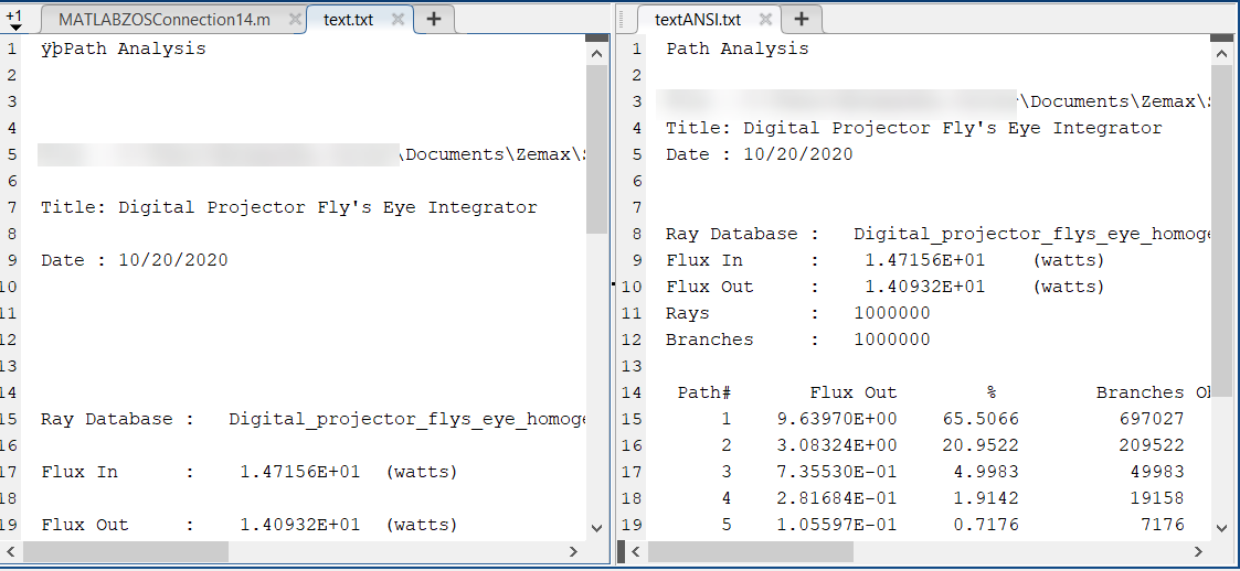
I have tested in Matlab and I see the output you have shown when I have Unicode selected for the Text File Encoding within OpticStudio. I'm not sure why, but Unicode seems to be adding some spaces. When I switch to ANSI, I do not see the same problem. Here is the output of both, with Unicode on the left-hand side.
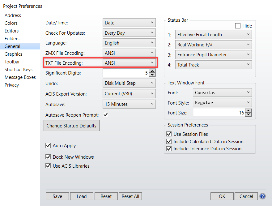
If you prefer the output on the right, you can update the setting by navigating to Setup...Project Preferences...General:
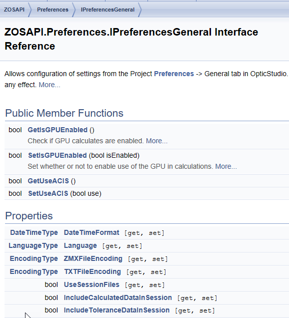
You can also change this setting through the API:
Let me know if you have any other questions about this!
Best,
Allie