Question

Batch Ray Tracing Vignetting Inconsistency


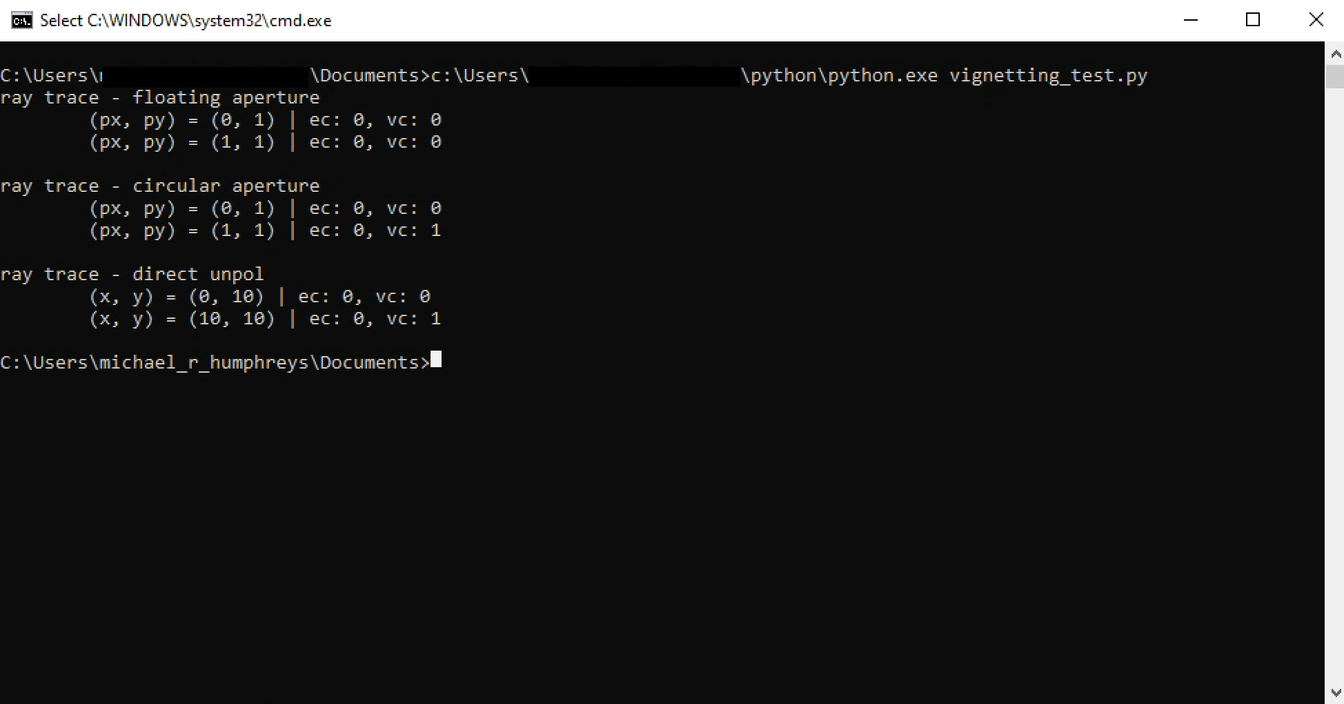
While analyzing the results of batch ray traces, I noticed that some rays seemed to be transmitted through the system that I did not believe should have made it. To test this, I set up a series of ray traces, all with the same set of input ray positions and direction cosines (no difference whatever). The only parameter I let vary between the traces was the final surface of the ray trace. In other words, my setup contained this line:

RayTraceData = raytrace.CreateDirectPol(total_rays_in_both_axes, ZOSAPI.Tools.RayTrace.RaysType.Real, 0,0,0,0,startSurface,endSurface);

where only endSurface was allowed to vary. I stepped endSurface through every surface and recorded the vignetteCode value of every ray. Plotting the results, I have found a few instances where a subset of the rays that vignette at the nth surface are not listed as vignetting at the n+1st surface. For example (see attached), the plot for surface 18 shows rays that were listed as vignetting at surfaces 7, 8, and 9, which are no longer listed on the plot for surface 19. This phenomenon happens again at the transition from surface 46 to 47. This is a problem, since once rays have vignetted in the system, they should remain vignetted throughout. I am wondering whether this a known bug, and more importantly, if there is a known workaround for keeping track of all rays that have vignetted at any surface in the system without having to ray trace to every surface individually. 


10 replies

Userlevel 3
Badge +4

Sympathizing with this post and trying to get resolution on this.  I have a similar problem.

Userlevel 6
Badge +2
  • Do all surfaces have a hard aperture (Circular or UDA) on them? 
  • Are there pickups on the semi-diameter? 
  • Are there multiple configurations? 
  • Are there ignored surfaces?

If you can convert from Direct to Normalized (Hx/Hy/Px/PY), what does the Single Ray Trace in the GUI show (under Analyze > Rays & Spots > Single Ray Trace) for vignetting and/or errors for this ray?  If you cannot convert, what does the ZPL with RAYTRACEX show?

If you can upload a file, that can help diagnose the issue and if it’s a bug, to let Zemax know.


Userlevel 3
Badge +4

Ok.. so I received the following explanation from Technical Support:

  1. Rays are not flagged by Vignetting or Error codes in ray tracing just because they are outside the circular STOP. 
    • If you trace a ray at Px = 1.0 and Py = 1.0, it will trace as if there were no STOP.  This ray would not be flagged as an error or as vignetted.
    • It is best practice to only trace rays inside the STOP
  2. It is the programmer’s / model builder’s responsibility to place an aperture at the Entrance / Exit pupil if you want to explicitly cause RAYTRACE (and similar) to throw an error / vignette code if the rays should be caught by OpticStudio
  3. The Clear Semi-diameter is not a substitute for setting an aperture.  The semi-diameter is used mostly for rendering images of the surfaces / lenses
  4. The ray trace GUI behaves similarly to (2) above.  It will also trace rays at Px=1.0, Py=1.0 without throwing a warning or an error.

-B

Hey Brian, if you are able to make the switch from DirectPol raytraces to DirectUnpol traces, then you might see this issue resolved. I changed nothing about my design, but decided to try abandoning polarization tracking on a whim and saw the bug vanish. 


-Devin

Userlevel 3
Badge +4

Thanks for the suggestions.

The issues remain for me using DirectUnpol traces.  I have both ZPL (see below) and ZOS-API code that confirms the issues above.

-B


! rayTraceSample
!
! Change the surface numbers in the rayx, rayy, and rayz for your own model

hx = 0
hy = 0
px = 1
py = 1
PRINT "Ray Input"
PRINT " (Hx, Hy) ", hx, " ", hy
PRINT " (Px, Py) ", px, " ", py

RAYTRACE hx, hy, px, py
PRINT "Ray Error Codes"
PRINT " Code Err ", raye()
PRINT " Code Vignette ", rayv()

PRINT "Ray Intercept at STOP"
PRINT " x ", rayx(1)
PRINT " y ", rayy(1)
PRINT " z ", rayz(1)

PRINT "Ray Intercept at Image"
PRINT " x ", rayx(7)
PRINT " y ", rayy(7)
PRINT " z ", rayz(7)


Userlevel 6
Badge +2

Hey Brian,

Based on a very simple system, I am getting the expected results for the vignetteCode with the ZOS-API.  One common mistake when running a ray trace is not putting a hard aperture on a surface and letting OpticStudio automatically re-calculate the Clear Semi-Diameter to try to get rays to pass through the system.  I suspect this is happening when looping from surface to surface in the original example.  The algorithm to automatically increase the Clear Semi-Diameter is an iterative algorithm that has round-off errors, especially if Fast Semi-Diameters is checked or a complex aperture with fine details is used.

The following Python code shows the ZOS-API working as expected for both SingleRayNormUnpol and SingleRayDirectUnpol:

import zosapi
zos = zosapi.App()
TheSystem = zos.TheSystem
ZOSAPI = zos.ZOSAPI

# create new sequential system
TheSystem = TheSystem.TheApplication.CreateNewSystem(ZOSAPI.SystemType.Sequential);

# make the system traceable with a finite size and some thickness
s1 = TheSystem.LDE.GetSurfaceAt(1);
s1.SemiDiameter = 10;
s1.Thickness = 1;
TheSystem.SystemData.Aperture.ApertureType = ZOSAPI.SystemData.ZemaxApertureType.FloatByStopSize

# raytrace without hard-aperture
tool = TheSystem.Tools.OpenBatchRayTrace();

print('ray trace - floating aperture')
px = 0; py = 1; t = tool.SingleRayNormUnpol(ZOSAPI.Tools.RayTrace.RaysType.Real, 2, 1, 0, 0, px, py, False, 0, 0, 0, 0, 0, 0, 0, 0, 0, 0, 0, 0, 0);
print('\t(px, py) = (%i, %i) | ec: %i, vc: %i' % (px, py, t[1], t[2]));
px = 1; py = 1; t = tool.SingleRayNormUnpol(ZOSAPI.Tools.RayTrace.RaysType.Real, 2, 1, 0, 0, px, py, False, 0, 0, 0, 0, 0, 0, 0, 0, 0, 0, 0, 0, 0);
print('\t(px, py) = (%i, %i) | ec: %i, vc: %i' % (px, py, t[1], t[2]));

# need to close your tool if making changes to system
tool.Close();
print('');
# make S1 a circular aperture
cas = s1.ApertureData.CreateApertureTypeSettings(ZOSAPI.Editors.LDE.SurfaceApertureTypes.CircularAperture)
cas._S_CircularAperture.MaximumRadius = 10
s1.ApertureData.ChangeApertureTypeSettings(cas);

# reopen tool and perform vignetted ray trace
tool = TheSystem.Tools.OpenBatchRayTrace();
print('ray trace - circular aperture')
px = 0; py = 1; t = tool.SingleRayNormUnpol(ZOSAPI.Tools.RayTrace.RaysType.Real, 2, 1, 0, 0, px, py, False, 0, 0, 0, 0, 0, 0, 0, 0, 0, 0, 0, 0, 0);
print('\t(px, py) = (%i, %i) | ec: %i, vc: %i' % (px, py, t[1], t[2]));
px = 1; py = 1; t = tool.SingleRayNormUnpol(ZOSAPI.Tools.RayTrace.RaysType.Real, 2, 1, 0, 0, px, py, False, 0, 0, 0, 0, 0, 0, 0, 0, 0, 0, 0, 0, 0);
print('\t(px, py) = (%i, %i) | ec: %i, vc: %i' % (px, py, t[1], t[2]));

print('')
print('ray trace - direct unpol')
x = 0; y = 10; t = tool.SingleRayDirectUnpol(ZOSAPI.Tools.RayTrace.RaysType.Real, 0, 2, 1, x, y, 0, 0, 0, 1, 0, 0, 0, 0, 0, 0, 0, 0, 0, 0, 0, 0);
print('\t(x, y) = (%i, %i) | ec: %i, vc: %i' % (x, y, t[1], t[2]));
x = 10; y = 10; t = tool.SingleRayDirectUnpol(ZOSAPI.Tools.RayTrace.RaysType.Real, 0, 2, 1, x, y, 0, 0, 0, 1, 0, 0, 0, 0, 0, 0, 0, 0, 0, 0, 0, 0);
print('\t(x, y) = (%i, %i) | ec: %i, vc: %i' % (x, y, t[1], t[2]));

# always close your tool
tool.Close();


Userlevel 3
Badge +4

@MichaelH  Thanks for your code and effort.

One common mistake when running a ray trace is not putting a hard aperture on a surface and letting OpticStudio automatically re-calculate the Clear Semi-Diameter to try to get rays to pass through the system.

This is exactly what I pointed out in this part of my post:

It is the programmer’s / model builder’s responsibility to place an aperture at the Entrance / Exit pupil if you want to explicitly cause RAYTRACE (and similar) to throw an error / vignette code if the rays should be caught by OpticStudio

Is there something else I am missing?


Userlevel 6
Badge +2

Hey Brian,

No, there is nothing else that is missing.  My only complaint is semantic about Zemax’s response.  For points 1, 2, & 3, the Zemax response read as if vignetting is only an issue for programming or for the actual Stop surface.

it is the programmer’s responsibility...to explicitly cause RAYTRACE (and similar) to throw an error

This is the case for every sequential file, regardless of if a “programmer” uses “RAYTRACE”.  If you use REAX or REAY in the MFE, you will get similar issues with checking for vignetting.

Also, the Zemax response only talks about the Stop, but as soon as you have off-axis field points, you need to place hard apertures on all surfaces, not just the Stop.

Basically, my rule of thumb is:

  • Floating apertures - during optimization before you have a final design candidate
  • Circular apertures - running analyses on a design candidate after optimization

The LDE has 2 great tools to Convert Semi-Diameters to Circular Apertures and Convert Semi-Diameters to Floating Apertures:


Userlevel 7
Badge +3

Oh brother, I know why this is hard. 😪

In sequential mode, all surfaces are treated as being infinite in extent. There are no limits placed on the domain of validity of an (x, y) coordinate on a surface. As long as the ray hits the surface, it is not vignetted. As long as it does not totally-internally-reflect, it is a valid ray trace.

That means the standard for a ray to be traced successfully is only that there is an intercept between the ray and the surface, (so the ray doesn’t miss the surface) and that TIR does not occur at that intercept. Otherwise, the ray gets traced and then passed onto the next surface for further tracing

Any other error checking is the responsibility of the user/programmer, as noted. I know that this sounds cold-hearted and not very customer-friendly, but it is sadly correct and the only way things can be. There’s no way the ray tracer knows that there’s some other condition that needs to be met...the user has to identify that condition explicitly. Written down that way, it sounds very harsh and unhelpful.

The conditions that OS supplies for you are the ‘Clear Aperture’ setting, associated apertures on surfaces, and the ‘Allow Hyperhemispheric’ switch. OS will detect that a ray hits outside the clear aperture, but will only kill the retrace if the ray hits a hard aperture. That’s your way to tell the code when to kill the ray.

So yes, you may have to post-process the ray data set to remove rays that trace accurately but are unwanted for other reasons.

Non-sequential objects are different because they are solid objects not infinite surfaces. If a ray misses object n, that’s it. That ray will take a different path than a ray that hits object n. But sequential surfaces are infinite...every ray either hits the surface or misses it. Those rays are terminated, and are not traced further. Of those that are traced, some TIR and are terminated. All other rays were successfully traced.

I’m not sure how helpful this post is, other than pointing out why things are the way they are. When I read the original post I was concerned that the same ray was being traced twice, with different results. That would be a bug, or at least worthy of a developer with source code access looking to see exactly what is happening down in the dungeons of the code.

HTH,

  • Mark
Userlevel 7
Badge +3

One other point. With some surfaces, there are more than one possible ray-surface intercept and the ray tracer needs to work out which one is correct. It almost always gets this right. For those very few cases where it gets it wrong, there is the ‘Allow Hyperhemipsheric’ switch to make the choice, or there are the ‘Alternate Even’ and ‘Alternate Odd’ surfaces. These will return the other intercept than the Standard versions do.

I can’t speak for Zemax support now, but we certainly used to treat any legitimate use of an Alternate surface type as a bug, even though it wasn’t strictly. The goal was to make every ray trace correctly with the normal surfaces, and use the Alternate Surfaces as a debugging tool. There may be something like that going on in your system, I don’t know but I raise it just so you’re aware.

Reply