API_Layout_plot_Python

  • 11 November 2023
  • 20 replies
  • 503 views

API support for the Cross-Section, 3D Layout, and Shaded Models is added to the OpticStudio API.  The support allow users to change the settings via the API and retrieve a static image.  Layouts in both sequential and non-sequential mode are supported. Some toolbar buttons, such as automatically setting camera viewpoints, will also be accessible via the API. 

Please download the following Python Standalone codes, including:

  1. PythonStandaloneApplication_SEQ_layout.py       (sequential mode and export 2D cross-section)
    • TheSystem.Tools.OpenCrossSectionExport()   # the core command 
  2. PythonStandaloneApplication_SEQ_3DViewer.py (sequential mode and export 3D viewer)
    • TheSystem.Tools.Open3DViewerExport()
  3. PythonStandaloneApplication_SEQ_ShadedModel.py (sequential mode and export shaded model)
    • TheSystem.Tools.OpenShadedModelExport()
  4. PythonStandaloneApplication_NSC_3D.py              (non-sequential mode and export 3D layout)
    • TheSystem.Tools.OpenNSC3DLayoutExport()
  5. PythonStandaloneApplication_NSC_ShadedModel.py (non-sequential mode and export shaded model)
    • TheSystem.Tools.OpenNSCShadedModelExport()

Let us use 2D cross-section image export as one example: here is the setting window of cross-section layout.
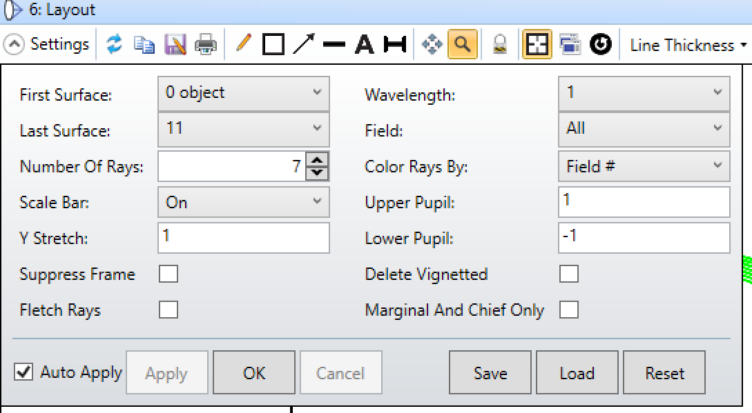
Now you can use API to access these settings: 

    TheSystem = TheApplication.PrimarySystem

    TheSystem.LoadFile(r"C:\Users\test\Double Gauss 28 degree field\Double Gauss 28 degree field.zmx", False) #load the targeted OS file

Left panel of settings window

myLayout = TheSystem.Tools.Layouts.OpenCrossSectionExport()

myLayout.StartSurface = 1

myLayout.EndSurface = TheSystem.LDE.NumberOfSurfaces - 1

myLayout.NumberOfRays = 7 

myLayout.YStretch = 1    

myLayout.FletchRays = False  # or True

Right panel of settings window

myLayout.Wavelength = -1  # Note that -1 means all wavelength !!!

myLayout.Field = -1      # Note that -1 means all fields 

# myLayout.ColorRaysBy = ZOSAPI.Tools.Layouts.ColorRaysByCrossSectionOptions.Fields        # choice 1

# myLayout.ColorRaysBy = ZOSAPI.Tools.Layouts.ColorRaysByCrossSectionOptions.Waves       # choice 2

myLayout.ColorRaysBy = ZOSAPI.Tools.Layouts.ColorRaysByCrossSectionOptions.Wavelength  # choice 3

myLayout.UpperPupil = 1

myLayout.LowerPupil = -1

myLayout.DeleteVignetted = False  # or True   

myLayout.MarginalAndChiefRayOnly = False # or True 


myLayout.SaveImageAsFile = True # or False (if you do not want to save the image)

myLayout.OutputFileName = r"C:\Users\test\Double Gauss 28 degree field_CS_5.jpeg"  # supported image format including jpeg, bmp, png.  # You select the path to save the exported image

myLayout.OutputPixelWidth =  1920 #  4096 and even bigger

myLayout.OutputPixelHeight = 1080 #  2400 and even bigger


Besides, the toolbar of Line Thickness is also supported:

# myLayout.SurfaceLineThickness = ZOSAPI.Tools.Layouts.LineThicknessOptions.Thinnest

# myLayout.SurfaceLineThickness = ZOSAPI.Tools.Layouts.LineThicknessOptions.Thin

myLayout.SurfaceLineThickness = ZOSAPI.Tools.Layouts.LineThicknessOptions.Standard

# myLayout.SurfaceLineThickness = ZOSAPI.Tools.Layouts.LineThicknessOptions.Thick 

# myLayout.SurfaceLineThickness = ZOSAPI.Tools.Layouts.LineThicknessOptions.Thickest 


# myLayout.RaysLineThickness = ZOSAPI.Tools.Layouts.LineThicknessOptions.Thinnest

# myLayout.RaysLineThickness = ZOSAPI.Tools.Layouts.LineThicknessOptions.Thin

myLayout.RaysLineThickness = ZOSAPI.Tools.Layouts.LineThicknessOptions.Standard

# myLayout.RaysLineThickness = ZOSAPI.Tools.Layouts.LineThicknessOptions.Thick

# myLayout.RaysLineThickness = ZOSAPI.Tools.Layouts.LineThicknessOptions.Thickest


Last but not least, the direct access of the R, G, and B data of exported image is supported also. For example, you could uncomment the following piece of code to obtain these data (i.e., rData, gData, bData). Note that you need to let  myLayout.SaveImageAsFile = False  

   # if (myLayout.RunAndWaitForCompletion()):

    #     ImageExportData = myLayout.ImageExportData

    #     if ImageExportData is not None:

    #         pixel = ImageExportData.GetImagePixel(512, 512)

    #         print(f"Pixel 512x512: {pixel.R} {pixel.G} {pixel.B}")

    #         rData = 0] * (1920 * 1080)

    #         gData = 0] * (1920 * 1080)

    #         bData = 0] * (1920 * 1080)

    #         ImageExportData.FillValues(1920 * 1080, rData, gData, bData)

    #         pixels = ImageExportData.Values

    #         print(pixelsl512, 512].ToString())


Hope you like this new object Layout under the Tools! Please feel free to modify the attached codes as you want, and please let us know if you have any questions. 

This is one of the biggest updates to the ZOS-API since adding POP support (and maybe since launching in 2015).  This is SUCH a long time coming and will be amazingly helpful.  

And just to be perfectly clear, this looks like it will be in the 2024 R1.0 release, so it’s not active yet.


Hi Michael,

Thank you very much for your clarification, yes it is for the 2024 R1 release.

Best regards,

Xianglei


Hi @Xianglei,

It looks like you are becoming the ZOS-API expert at Zemax so I’ll raise this request to you.

It’s probably too big of an ask for the 24R1 release, but another extremely frustrating aspect of the ZOS-API (which should actually be easier to for the developers to implement vs the Layout API) is you can’t get direct access to all 29 data points in a Non-Sequential ray trace without saving a ZRD file to disk and parsing this file (this is slow, sometimes problematic with read/write capabilities, and developers forget to delete the ZRD).

In the IBatchRayTrace interface, there are IRayTraceNSCData and IRayTraceNSCSourceData (they have the same out parameters with their ReadNextSegment methods).  The following are the lack of outputs for each interface compared to saving a full ZRD file:

  • out int hitFace
  • out RayStatus status
  • out int xybin
  • out int lmbin
  • out double xNorm
  • out double yNorm
  • out double zNorm
  • out double index
  • out double startingPhase
  • out double phaseOf
  • out double phaseAt

The lack of hitFace means we can’t do something like the NSC Sag Map, the lack of status means we can’t see if the ray has an error, the lack of xybin/lmbin means we can’t recreate a detector, the lack of Norm values means we can’t calculate the Angle of Incidence, and the lack of index means we can’t calculate optical path length.  All these values can be accessed via the ZRD but it would be extremely useful to add a ReadNextSegmentFull to the IRayTraceNSCData and IRayTraceNSCSourceData interfaces so we can access all these values without writing to disk.


@MichaelH I have been looking at this issue. I hope to have news soon. We are always trying to improve functionality. In the meantime, 24R1 has some new functionality that you probably will like. I will post about the new functionality when 24R1 is released. 


Hi team - I’m temporarily hiding this post until the release. We can continue the discussion after 2024 R1 is publicly available :)


I put the summary codes for the sequential 3D viewer layout plot for those who want to check the commands quickly.


myLayout = TheSystem.Tools.Layouts.Open3DViewerExport()

myLayout.StartSurface = 1

myLayout.EndSurface = TheSystem.LDE.NumberOfSurfaces - 1

myLayout.SaveImageAsFile = True      

myLayout.OutputFileName = r"C:\Users\xianliu\OneDrive - ANSYS, Inc\testing_OD\2023\6004\SEQ\Double Gauss 28 degree field_3DViewer.png" #bmp, jpeg


myLayout.OutputPixelWidth = 1920

myLayout.OutputPixelHeight = 1080

myLayout.NumberOfRays = 7

myLayout.Wavelength = -1  # 0 or -1 means all wavelength

myLayout.Field = -1      # Pass (10 gives the same result as 3)

myLayout.RayPattern = ZOSAPI.Tools.General.RayPatternType.XYFan    # XFan, YFan, Ring, List, Random, Grid

myLayout.ColorRaysBy = ZOSAPI.Tools.Layouts.ColorRaysByOptions.Fields    # Waves, Wavelength

myLayout.DeleteVignetted = True 

myLayout.HideLensFaces = True   

myLayout.HideLensEdges = True  

myLayout.HideXBars = True       

myLayout.DrawParaxialPupils = True     


myLayout.DrawRealEntrancePupils = ZOSAPI.Tools.Layouts.RealPupilOptions.Pupils_Off # Pupils_4 Pupils_8 Pupils_16 Pupils_32

myLayout.DrawRealExitPupils = ZOSAPI.Tools.Layouts.RealPupilOptions.Pupils_Off, # Pupils_4 Pupils_8 Pupils_16 Pupils_32

myLayout.FletchRays = True    

myLayout.SplitNSCRays = True  

myLayout.ScatterNSCRays = True

myLayout.SurfaceLineThickness = ZOSAPI.Tools.Layouts.LineThicknessOptions.Thinnest #  Thin , Standard Thick Thickest

myLayout.RaysLineThickness = ZOSAPI.Tools.Layouts.LineThicknessOptions.Thinnest # Thin , Standard Thick Thickest

myLayout.CameraViewpointAngleX = 0 #AngleY AngleZ

myLayout.ConfigurationAll = True  # Current

myLayout.ConfigurationOffsetX = 0 # OffsetY OffsetZ

myLayout.RunAndWaitForCompletion()

myLayout.Close()


I put the summary codes for the sequential ShadeModel layout plot for those who want to check the commands quickly.

myLayout = TheSystem.Tools.Layouts.OpenShadedModelExport()

myLayout.SaveImageAsFile = True

myLayout.OutputFileName = r"C:\Users\xianliu\OneDrive - ANSYS, Inc\testing_OD\2023\6004\SEQ\Double Gauss 28 degree field_Shaded.jpeg" 

myLayout.StartSurface = 1

myLayout.EndSurface = TheSystem.LDE.NumberOfSurfaces - 1

myLayout.NumberOfRays = 10

myLayout.OutputPixelWidth =  4096   #  1920

myLayout.OutputPixelHeight = 2410 #   1080

myLayout.RayPattern = ZOSAPI.Tools.General.RayPatternType.XYFan   #  XFan, YFan, Ring, List, Random, Grid

myLayout.ColorRaysBy = ZOSAPI.Tools.Layouts.ColorRaysByOptions.Fields        # Waves, Wavelength

myLayout.Opacity = ZOSAPI.Tools.Layouts.OpacityOptions.Ignore        # Consider, All50Percent, Color12

myLayout.Background =ZOSAPI.Tools.Layouts.BackgroundOptions.White      # Black, Red, Gradient03

myLayout.Wavelength = 1  # 0 or -1 means all wavelength

myLayout.Field = -1      # Pass (10 gives the same result as 3)

myLayout.DrawSection = ZOSAPI.Tools.Layouts.DrawSectionOptions.P100 # P75 P50 P25

myLayout.AngularSegments = ZOSAPI.Tools.Layouts.NumberSegmentsOptions.S_8  # S_16 S_32 S_64 S_128

myLayout.RadialSegments = ZOSAPI.Tools.Layouts.NumberSegmentsOptions.S_8   # S_16 S_32 S_64 S_128

myLayout.Brightness = ZOSAPI.Tools.Layouts.BrightnessOptions.P10  # P50 P100

myLayout.FletchRays = True     

myLayout.DeleteVignetted = True

myLayout.SplitNSCRays = True   

myLayout.ScatterNSCRays = True 

myLayout.ConfigurationAll = True   # Current

myLayout.Configuration = True # pass

myLayout.ConfigurationOffsetX = 0 # OffsetY OffsetZ

myLayout.CameraViewpointAngleX = 0 # AngleY AngleZ

myLayout.RunAndWaitForCompletion()

myLayout.Close()


I put the summary codes for the Non-sequential Shaded Model layout plot for those who want to check the commands quickly.


myLayout = TheSystem.Tools.Layouts.OpenNSCShadedModelExport()

myLayout.SaveImageAsFile = True     

myLayout.OutputFileName = r"C:\Users\xianliu\OneDrive - ANSYS, Inc\testing_OD\2023\6004\NSQ\Test2B_QCon_NONSEQ_Coated_ShadedModel_demo.png"

myLayout.OutputPixelWidth = 1920

myLayout.OutputPixelHeight = 1080

myLayout.DetectorPixelColorMode = ZOSAPI.Tools.Layouts.DetectorPixelColorOptions.DoNotColorIndividualPoints  # ByRaysOnLayout ByLastAnalysis

myLayout.Filter = None

myLayout.RayDatabase = None

myLayout.RayTrace = ZOSAPI.Tools.Layouts.RayTraceOptions.UseRays   # LightningTraceAvgWavelength, LightningTraceTrueColor, InverseFalseColorIrradiance

myLayout.DetectorDisplayMode =

ZOSAPI.Tools.Layouts.DetectorDisplayModeOptions.Consider # GreyScaleFlux, InverseGreyScaleFlux, FalseColorFlux, InverseFalseColorFlux, GreyScaleIrradiance, InverseGreyScaleIrradiance, FalseColorIrradiance

myLayout.ColorRaysBy = ZOSAPI.Tools.Layouts.ColorRaysByNSCOptions.SourceNumber   # WaveNumber, ConfigNumber, Wavelength, SegmentNumber

myLayout.Background = ZOSAPI.Tools.Layouts.BackgroundOptions.White     # Red, Black, Gradient10, Color24, DarkBlue

myLayout.Brightness = ZOSAPI.Tools.Layouts.BrightnessOptions.P10       # P50, P100

myLayout.Opacity = ZOSAPI.Tools.Layouts.OpacityOptions.All50Percent     # Ignore Consider

myLayout.CameraViewpointAngleX = 0 # CameraViewpointAngleY, CameraViewpointAngleZ

myLayout.UsePolarizaion = True

myLayout.FletchRays = True   

myLayout.SplitNSCRays = True   

myLayout.ScatterNSCRays = False

myLayout.ConfigurationAll = True  # ConfigurationCurrent

myLayout.ConfigurationOffsetX = 0 # ConfigurationOffsetY, ConfigurationOffsetZ

myLayout.RunAndWaitForCompletion()

myLayout.Close()


I put the summary codes for the Non-sequential 3D layout plot for those who want to check the commands quickly.


myLayout = TheSystem.Tools.Layouts.OpenNSC3DLayoutExport()

myLayout.SaveImageAsFile = True        

myLayout.OutputFileName = r"C:\Users\xianliu\OneDrive - ANSYS, Inc\testing_OD\2023\6004\NSQ\Test6B_QType0_NONSEQ_Coated_3D.png" # bmp, jpeg

myLayout.OutputPixelWidth = 1920

myLayout.OutputPixelHeight = 1080


myLayout.RayDatabase = NoneQ

myLayout.Filter = None

myLayout.RayTrace = ZOSAPI.Tools.Layouts.RayTraceOptions.UseRays                      # LightningTraceAvgWavelength, LightningTraceTrueColor

myLayout.ColorRaysBy = ZOSAPI.Tools.Layouts.ColorRaysByNSCOptions.SourceNumber # WaveNumber, ConfigNumber, Wavelength, SegmentNumber


myLayout.UsePolarizaion = True

myLayout.FletchRays = True  

myLayout.SplitNSCRays = True  

myLayout.ScatterNSCRays = False

myLayout.CameraViewpointAngleX = 0 # CameraViewpointAngleY, CameraViewpointAngleZ

myLayout.ConfigurationAll = True  # ConfigurationCurrent


myLayout.ConfigurationOffsetX = 0 # ConfigurationOffsetY ConfigurationOffsetZ

myLayout.RunAndWaitForCompletion()

myLayout.Close()


Hey Xianglei,

Thanks for posting the detailed examples.  

One immediate feedback about this implementation is we don’t have access to the Zoom or Pan capabilities.  Right now, the only way to control the Zoom or Pan of any layout is to use a mouse; this is saved in the ZDA file but you can’t precisely recreate the Zoom or Pan if you change specific settings (like First Surface or Last Surface) or if you open up a new window.

To make this feature complete, we need access to set the Zoom & Pan programmatically.  Hopefully this can be incorporated into a future update in the very near future.


Hey Michael,

Thank you very much for your inputs here, which is fantastic to add Zoom or Pan in the API.

Best regards,

Xianglei


nice feature. can I change size of axis marker and visualize size marker?

on taked picuture “size marker” hidden and “axis marker” relative small

in zemax:

in saved image


Hello @Xianglei,

In future release, do you think it would be possible to set the rays shown in the 3D viewer per API?

Same way it is been done for batch ray tracing.

It would be great, to be able to explore in the viewer, the ray bundle been batch ray traced.

Best regards

Dimiter


@Xianglei 


Excellent work, and amazing feature.

I’d like to double down on what @MichaelH said. We have the Pan attributes but it would really be awesome to also have the Zoom. I can already imagine the nice animations we could create *_*

Take care,


David


This is a great new feature, well done. I’d love to see all the little gaps in ZOS-API being aggressively filled so that ZOS-API really does allow 100% of the things done by mouse and keyboard. Right now we’re at around 95% and those last few % are real killers if you’re on a time budget and you need one of those few missing items.

  • Mark

Hey Dimiter,

If you’re in sequential mode, look at the Raylist.txt in Zemax\Miscellaneous folder and then change the RayPattern setting to List.  By default, the Raylist.txt will trace rays to the normalized pupil coordinate for the specified field, but if you want direct ray tracing, you start the Raylist.txt with the EXPLICIT keyword and then define your XYLMN + wlum.

If you’re in non-sequential mode, you can define your initial rays in a Source File and then just make sure the # Layout Rays match the number of rays defined in your Source File.


Hi Michael,


Thank you for the great hint!

It solves exactly what i needed. It feels slightly like a life hack but I am happy with it.


Best regards Dimiter


Hi,

I tried the code for sequential layout previously and it was working well. But recently, the software was updated to Ansys Zemax OpticStudio 2024 R1.03 and ran into the following error when calling ‘Layouts’:

 myLayout = TheSystem.Tools.Layouts.OpenCrossSectionExport()
AttributeError: 'SystemTools' object has no attribute 'Layouts'


Wondering if anyone has this issue as well?


Regards, Ai Ping


Hi
I’m continuing as to what Ai Ping observed.  I’m using the API with OpticStudio 2024 R1.02 and the Layout being returned from TheSystem.Tools.Layouts.OpenCrossSectionExport() is returning a NULL reference.


Is there anything that I'm missing to make this work?


Thanks.

B.


***

All Set. Resolved The Issue. GDI will complain about an illegal path for filename. What’s weird is that the call to IsValidFileName returns false when giving a legal filename with a path. If I just give a filename without a path then IsValidFileName returns true but then GDI exception occurs.

BTW, I still can’t create a OpenCrossSectionExport() for some reason.

***

FYI, I switched to using OpenShadedModelExport() and I’m now getting a Layout object.


However...I’m know getting an exception when I call RunAndWaitForCompletion().


The exception is : “A generic error occurred in GDI+”

Using the API library in C# with .NET frame 4.8.1 and OpticStudio 2024 R1.02


Thanks
B.


Reply