Join us for our monthly “Ask an Engineer” event! On January 19th at 8am PST, Hui Chen will be answering your questions about Gaussian Beam Propagation. This event will be hosted on this thread in text form with a focus on the spotlighted topic…
Topic: Gaussian Beam Propagation in OpticStudio
Dates: January 10th - January 19th
Live Discussion Time: 8am - 9am PST, January 19th
Engineer:@Hui Chen - Senior Application Engineer at Ansys
Submit your questions for Hui as a reply to this thread between now and the end of the event. Questions added to the discussion will be answered starting at 8am Pacific on January 19th. Once the event is concluded, the thread will be closed.
If your question pertains to a particular file, the question may be moved to a private support case. In that situation, your license support status will be considered.
The laser system I work with uses a square beam profile. I’ve searched high and low on the help section and knowledge base tools and have not saw how I can define a square laser source. Is it even possible?
Jack
Hello,
1. The laser equipment outputs Gaussian laser through the fiber. Is the fiber core diameter equal to the beam waist diameter? 2. Does ZEMAX have a way to simulate multi-mode Gaussian laser output with a fiber diameter of 200-600um?
Hi,
I wanted to ask about POP tool for calculating coupling efficiency. Is there a possibility to make a graph of coupling efficiency vs. e.g. beam diameter or some other parameter using this tool?
NK
Hi everyone! I'm online for the next hour answering your questions on modeling Gaussian beam propagation using OpticStudio. In you have any questions related to this topic, send them as a reply to this thread.
Thank you Jack, 522721806 and Naku for posting your questions. I’ll address them in the order the questions were posted. I’ll also post some FAQs about the tool.
Hi @Jack.Sontag,
POP provides many different options for definition the initial beam. You can find it explained in the help file at The Analyze Tab (sequential ui mode) > Laser and Fibers Group > About Physical Optics Propagation > Defining the Initial Beam.
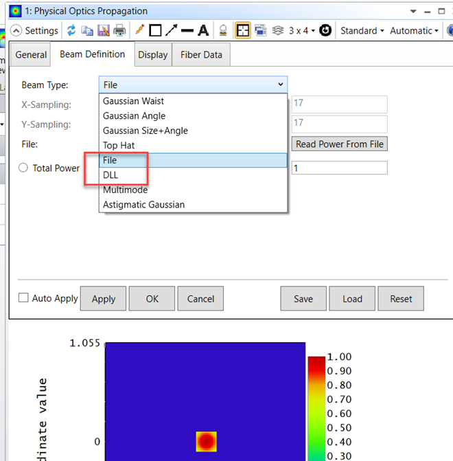
If the beam has a customized distribution, say a square beam profile, or a beam profile with a customized intensity distribution, you might want to consider using File or DLL option to create your own initial beam. File option uses POP’s native ZBF file format, whereas DLL options allows user to define a beam using an external program.
If this square laser source profile is caused by a square aperture clipping the laser beam, you can apply a square aperture on a surface and save the beam profile on that surface as a ZBF file. This saved ZBF with square shape can later be used in another system as the initial beam using the POP/File option. This is the spot I showed below.
Hi @522721806,
Regarding your first question, the Beam waist POP asks for is the 1/e2 radius if the beam profile is Gaussian. Fiber Mode Field Diameter (MFD) is typically defined as the diameter where the intensity drops to 1/e2 of the peak intensity. Since POP beam size is the half width or the 1/e2 radius, you can use MFD/2 as the beam waist size. Depending on your fiber, the 1/e2 Mode Field Diameter may be larger than the core diameter.
Regarding your second question, you can certainly model a multimode Gaussian laser using POP. POP provides many different options to define the initial beam, one of them is multimode, which consists of a sum of any number of other beams. You can find how to use POP/Multimode option to define the initial beam in the help file at The Analyze Tab (sequential ui mode) > Laser and Fibers Group > About Physical Optics Propagation > Defining the Initial Beam > Multimode
Hi @naku,
You can use POPD data 0 to return the coupling efficiency computed by POP. In general, to plot the change of an operand value vs a parameter, we recommend using the Universal Plot tool. In that tool you can assign a lens prescription data as the Dependent variable A, and assign the operand value as the Independent variable B, and plot the change of B vs A. But in this case it won’t work because the beam waist size entered in POP analysis window is not exposed to the Dependent variable list in the Universal plot analysis.
So you will need to get this curve, POP coupling efficiency vs beam waist, using ZPL macro or API. In the ZPL macro, you can set up a For loop, use ZPL keyword MODIFYSETTINGS to vary beam waist, and then use POPD data 0 to return the coupling efficiency. You can then plot the curve using ZPL macro or just save the data to a text file and plot it using an external program. The macro will look something like below:
For i, 1, N, 1
w0(i) = i
# change POP.CFG to vary the beam waist size w0
MODIFYSETTINGS popCFG$, POP_PARAM1, w0(i)
MODIFYSETTINGS popCFG$, POP_PARAM2, w0(i)
Update
OPENANALYSISWINDOW POP, popCFG$
C = OCOD("POPD")
E = OPEV(C, 0, 0, 0, 0, 0, 0)
CouplingEffi(i) = E
Print E
NEXT
OpticStudio Sequential Mode provides two analysis features that enable you to launch a Gaussian beam and analyze its characteristics as the beam propagates in the optical system. They are
the Paraxial Gaussian Beam analysis
the Physical Optics Propagation analysis
OpticStudio uses terms such as Waist and Angle to describe a Gaussian beam. Beam Size, Divergence and Rayleigh Range are used to report the beam characteristics as it propagates from surface to surface. If you want to know how these terms are defined in OpticStudio you can find a Gaussian beam FAQ in our Knowledgebase at https://support.zemax.com/hc/en-us/articles/1500005578622-OpticStudio-Gaussian-Beam-FAQ
In general, you can use three different approaches to model Gaussian beam propagation in OpticStudio:
The ray-based approach
Paraxial Gaussian Beam analysis
Physical Optics Propagation
In ray based approach, you can turn on the Apodization settings under System Explorer to create a Gaussian amplitude variation over the pupil. If you are inside Rayleigh range where beam size does not vary significantly over distance, you can model this using a collimated ray bundle. If you are far outside Rayleigh range where the beam size grows almost linearly with the distance it travels, you can model it using a point source.
The Paraxial Gaussian Beam analysis is an interactive feature that works as a “calculator” that quickly computes Gaussian beam characteristics. This feature computes ideal and mixed mode Gaussian beam data as a given input beam propagates through the lens system.
Physical Optics Propagation (POP) tool models optical systems by propagating wavefronts. The beam is represented by an array of discretely sampled points, analogous to the discrete sampling using rays for geometric optics analysis. The entire array is then propagated through the free space between optical surfaces. Out of the 3 approaches, POP is the most complex and most comprehensive tool. The physical optics model is generally more accurate at predicting the detailed amplitude and phase structure of the beam away from focus than conventional ray tracing. It allows very detailed study of arbitrary coherent optical beams, including:
Gaussian or higher order multi-mode laser beams of any form (beams are user definable).
Beams may be propagated along any arbitrary field position (skew beams).
Amplitude, phase, and intensity may be computed at any surface in the optical system.
Effects of finite lens apertures, including spatial filtering, may be modeled.
Accurate computation of propagation through any optical component OpticStudio can model via ray tracing.
There is a series of 3 articles in our Knowledgebase that discusses how to use the above 3 approaches to model Gaussian beam propagation. You can find them in our Knowledgebase under Laser & Fibers/Gaussian beams at https://support.zemax.com/hc/en-us/sections/1500001182822-Gaussian-Beams
Hi All,
Thanks for participating in this Ask An Engineer event! I’ll be signing off soon but you can continue to post on this thread if you have any questions or would like to know more about modeling Gaussian beam propagation in OpticStudio.
We will make this Ask An Engineer a monthly event. If you have any topics that you are interested in learning, please share your thoughts with us under the Ask An Engineer announcement post.
Have a wonderful day and see you all next time!
Hi Mam, I have LED with spec sheet, I would like to study and analyze its profile at different places, i mean i wish to see how it changes as light radiate from one place to other, even after passing through different elements like dichroic filters etc,. Can you please give ideas or demonstration on this.
@Ebi Hi Ebi,
Thank you for posting your question here!
How to model this LED beam propagation in your system will depend on the nature of the LED source and what analysis results you are trying to get. If the source is highly coherent and if diffraction effect are of interests, you might want to consider Physical Optics Propagation tool. Inside POP, you can define the initial beam using several options provided. Most frequently used options are the Gaussian Waist where you specify the starting beam waist based on the 1/e2 intensity radius provided by the spec, or the Gaussian Angle where you enter the beam divergence angle based on the NA of the source emission.
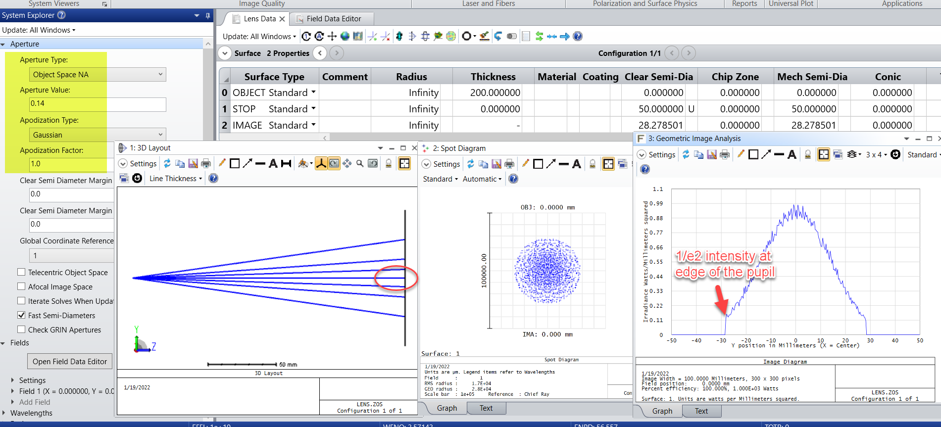
However, most LED light comes from spontaneous emission which is not spectrally coherent. In that case you can use geometric rays to model the LED emission and beam propagation in your system. For example, if the spec says the LED emission has a 1/e2 NA of 0.14, then you can set the Aperture as Object Space NA and turn on the Apodization and set the Apodization factor G =1. This will then create a Gaussian intensity profile with the 1/e2 intensity point at the edge of the pupil.