The STAR tools featured in Ansys Zemax OpticStudio Enterprise are designed to primarily be applied to sag-based surfaces to enable you to quantify the effects of multiphysics data on the optical performance of your system. When you use STAR to import structural FEA data onto a diffractive surface such as Diffraction Grating and phase surface, the diffractive power of these idealized surfaces is ignored and causes the surfaces to work as a normal transmission or mirror surface. While this can be unexpected at first, it is not a bug but a result of the STAR’s specification to provide real-world design insights using multiphysics data.
The new Component RBMs tool takes the calculated rigid body motions (RBMs) of the optical components and converts them to Coordinate Breaks in the Lens Data Editor (LDE). The feature allows you to set the decenter and tilt of specific components by extracting from the original FEA data set.

I will explain the benefits of the Component RBMs tool with the following sample design.
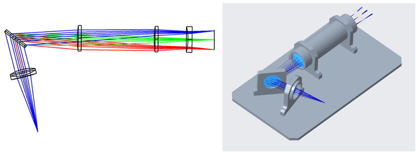
The sample file of the optical system can be downloaded from this KBA “How to build a spectrometer - implementation – Knowledgebase (zemax.com)”. The optomechanical design file as STEP is also attached to this community post.
Ansys Mechanical was used to perform the FEA for thermal-structural analysis of the optomechanical design. A part of the base plate (blue area in the following figure) was fixed, and the overall environmental temperature was set to 85 degrees.
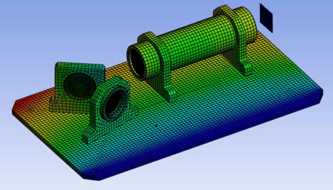
Thermally induced linear expansion of the mechanical components changes the relative position of optical components. FEA data output for OpticStudio is included in the OpticStudio project file attached to the post.
You can confirm the optical components moved radially around the fixed part of the base plate with Multiphysics Data Viewer. The RBM values were checked by Fit Assessment tool.

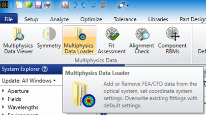
Next, the structural FEA data set was loaded into OpticStudio with the Multiphysics Data Loader tool. When the data is loaded, you can see that OpticStudio ignores the diffraction power of the Diffraction Grating surface which results in the stop of raytracing after the Diffraction Grating surface. By adding the dummy surface after the grating surface, we can confirm the ray's propagation that ignores diffraction power and miss the next lens.

Deselect the checkbox in the Fitted Deformation and the Extracted RBMs columns in the Surface Deformation Summary to ignore the effect of the FEA data of the Diffraction Grating surfaces. After updating, the rays will be traced through the grating works as normal, but the deformation and displacement are not taken into account.
The RBM information can be considered for the Diffraction Grating surfaces by using the Component RBMs tool. This tool works by replacing the RBMs (displacement and tilt) of the defined components with Coordinate Breaks in the LDE. The process is shown in the following figure:
- The surfaces of interest are selected and defined as one optical component
- The component RBMs from the surfaces in this range are calculated
- The components RBMs are subtracted from the surfaces and added to the LDE as Coordinate Break Surfaces.
Note: This process is irreversible, so it is recommended that you create a new file as recommended by the prompt that appears after clicking “Add Component RBMs as Coordinate Breaks.”
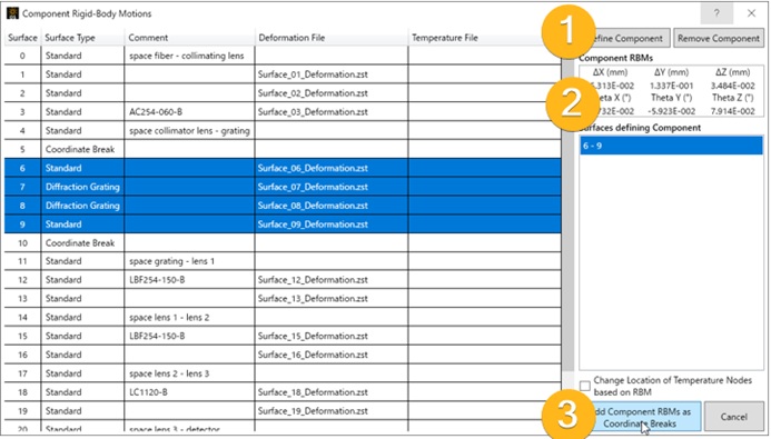
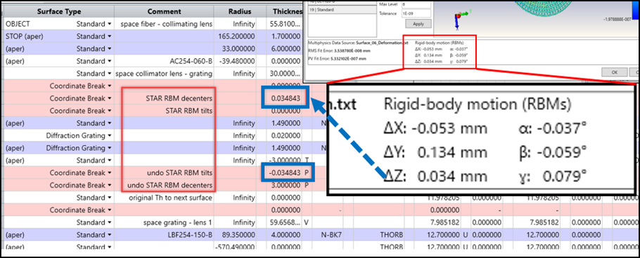
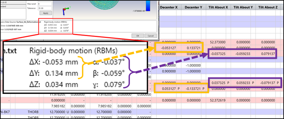
The Component RBMs tool automatically generates Coordinate Breaks and inserts them into the LDE. The remaining deformation datasets are then applied to the other Standard surfaces in the optical design. After loading the other datasets into the system, it is possible to analyze the shift and size change of the spot due to the "displacement" of optical components including the diffractive components.
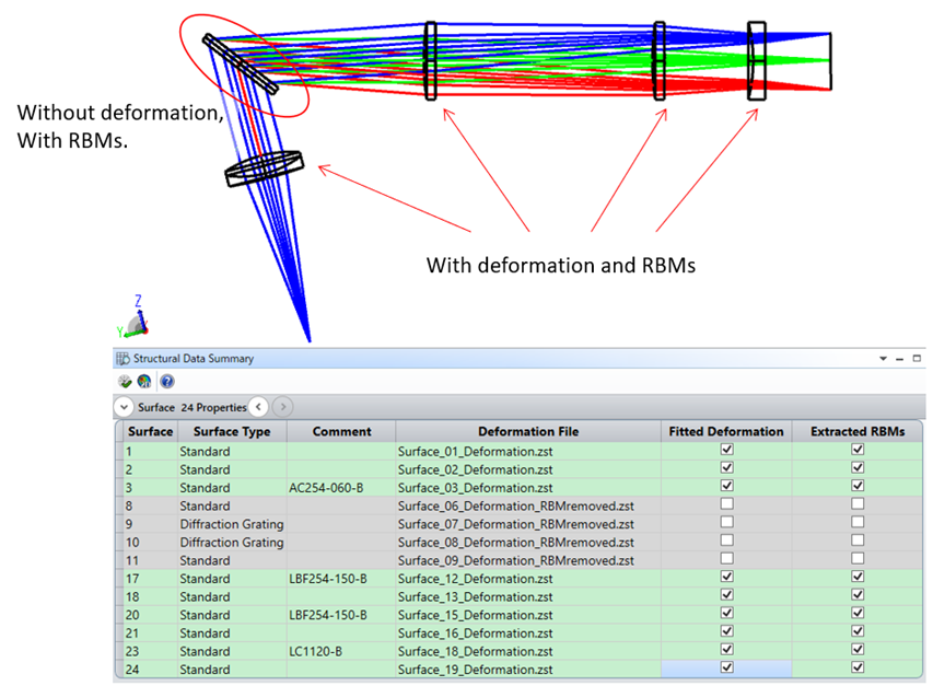
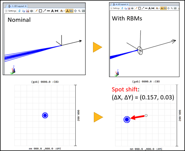
As described above, this workflow enables you to analyze the motion effects of diffraction gratings (and other non-sag-based surfaces) as part of your STOP analysis. However, the effects of surface deformation of the diffraction grating surface is not considered. That is, the surface is flat, and the period, direction, and structure of the grating are ideal. While not a complete STOP analysis for diffractive optical systems, this can provide important design insights into your system.

