Yes, STAR data can affect the vertex thickness and air gaps between lenses. Deformation data imported with STAR can contain position changes for the surface. If the surface moved in the FEA analysis, that movement is captured in the FEA deformations data. So, when users apply the FEA data set, they get both movement of the surface (rigid body motions) and higher-order deformations. This can change the position of the surface, and thus the vertex thickness of a lens.
The raytrace sees all of the deformation data, including rigid-body motions (RBMs). The deformations are accurately drawn in the Layout plots, and the STAR analysis tools give various options for plotting the deformations.
Rigid-body motions contained within the deformation data do not change the Thickness value reported in the Lens Data Editor, however. Certain other reported parameters, such as the global vertex of the part, are also unchanged by RBMs stored in the deformation data.
Currently, we report out the rigid-body motions in the Structural Data Summary. If we wanted to measure the lens thickness in an optical system with STAR data applied, we would have to carry out the following steps:
- Check the thickness between the two surfaces using the Thickness value in the Lens Data Editor.
- Look at (or retrieve) the DZ value of the calculated RBMs for the two surfaces, in the Deformation Data Summary.
- Combine that information into the lens thickness.
(This could all be done automatically with the ZOS-API, of course.)
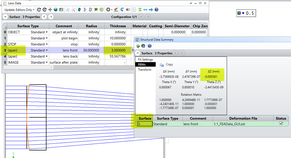
An example is shown below. In this case, the lens is 3.0 mm thick. I've added deformation data to the front of the lens. The reported dZ value in the Structural Data Summary is -0.000581. This is in local coordinates of surface 3, so that is motion to the left. So we could argue that the new vertex thickness of the part is (3 + 0.000 581) = 3.000 581 mm, because the lens is now thicker.
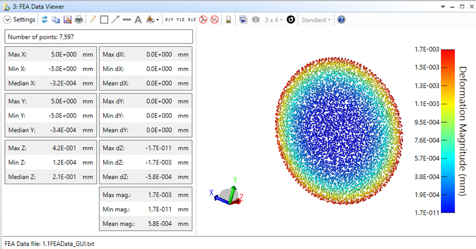
There is one subtlety here. The dZ that we retrieve for the RBMs is just the median of all the deformations, so we have to be careful how we use it. In this artificial case, all the deformations are in the -Z direction, but there is actually zero surface shift at the vertex of the surface. (You can see this by using the Inspect FEA Data tool, as shown below.) For realistic data, this shouldn't be a large problem because after removing any RBMs, the remaining deformations are unlikely to have significant median values. It is worth checking, though, that the reported dZ corresponds to the deformation value at the vertex of the lens.