I’m currently modelling an imaging system in sequential mode and want to check the effect of a beamsplitter quoted with a lambda/4 surface flatness and lambda wavefront error. As an approximation, is there a simple way to introduce the wavefront error at a dummy surface used to represent the beamsplitter?
If I wanted to more accurately account for the surface flatness in reflection, would I need to use non-sequential mode? And how would I incorporate this property into the surface in that case?
The problem is that while people will tell you that the compoent is 'flat to lambda/4' or whatever, you need to know how the aberration is distributed. If it's a nice low-order focus error then it can be easily compensated by a focal shift, and the higher-order and less-rotationally-symmetric the lambda/4 is, the less you're able to correct it.
I think that it is quite equivalent to tolerancing. The point to figure out is what does the lambda/4 mean? Is it a peak-to-valley error, is it a RMS? What would model best this error? This comes down to how it is measured and how it is manufactured.
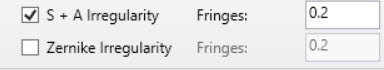
To tolerance the irregularity in OpticStudio, there are basically two choices: model the irregularity as a sum of spherical and astigmatic terms or model the irregularity with a Zernike surface.
In both cases, you can apply that error on the beamsplitter surface and then run the tolerancing. I have attached an example.
If you add a SAVE operand in the tolerancing, it will save the system at - tol and + tol.
The files are saved in the same folder as your file and they are called TSAV_MAX_0001.ZMX, ...
For more information on the Zernike terms, have a look at those articles:
The problem is that while people will tell you that the compoent is 'flat to lambda/4' or whatever, you need to know how the aberration is distributed. If it's a nice low-order focus error then it can be easily compensated by a focal shift, and the higher-order and less-rotationally-symmetric the lambda/4 is, the less you're able to correct it.