

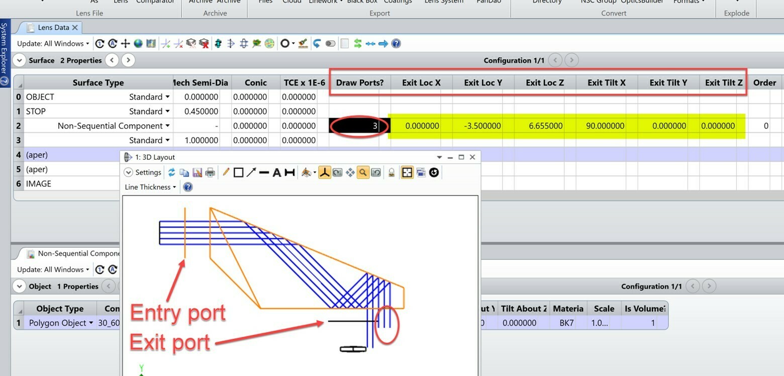
Mixed mode operation comes handy when modeling Sequential system that includes objects with complex geometries, for example prisms with many facets or CAD objects. In those situations, user can insert a Non-Sequential Component (NSC) surface in the Sequential model and perform mixed-mode ray tracing. The advantage is that though rays are traced non-sequentially within the NSC group, user still has access to many GUI analysis tools only Sequential mode can offer. This mixed-mode ray tracing allows you to take advantage of both Sequential and Non-Sequential ray tracing. However, there are certain rules to follow when running mixed-mode ray tracing. One common error seen when debugging mixed-mode ray tracing issue is the Entry and Exit port location. The NSC objects need to be properly enclosed between the Entry and Exit port. If rays hit the NSC object before reaching the Entry port, or if rays reach the Exit port before hitting all or part of the NSC object, you will not see rays interact with the NSC objects properly. This is because rays need to enter the NSC section through the Entry port, interact with the NSC objects, and then exit the NSC section via the Exit port. Most of the issues seen in mixed-mode ray tracing are caused by the improper placement of the Entry or Exit port. In the Lens Data Editor, if you set the Draw Ports? parameter to 3, OpticStudio will draw both Entry and Exit ports location in the 3D Layout to help you visualize. For example, in this prism setup below, some rays at the bottom right, highlighted in red circle below, miss the Exit port. Therefore you see only part of the beam is able to exit the NSC section and the part that misses the Exit port will be terminated. You can also run a Single Ray Trace to follow one specific ray surface by surface and within the NSC group to troubleshoot its ray path. The Exit port location can be adjusted via the six parameters highlighted in yellow.
A detailed description on things to watch out for when running mixed-mode ray tracing can be found in the help file at The Setup Tab > Editors Group (Setup Tab) > Non-sequential Component Editor > Non-sequential Overview > NSC ray tracing in mixed mode (with entry and exit ports)
