[Webinar] Zemax and Lumerical: Part 2 - From Nano-scale to Macro-scale Optics and Back [Q&A]


This thread will be used to collect questions before the webinar, and to answer any questions we received during the webinar. Feel free to post your questions! 

Be sure to subscribe to this thread if you want to see additional discussion regarding this topic. The thread will be open to comments through Friday, May 27th.


bThe event has concluded]


Date: Thursday, May 19th

Time: 6:00am PST & 11:00am PST

Presenters:

  • Shin-Sung Kim, Manager Application Engineering
  • Csilla Timar-Fulep, Senior Application Engineer

Abstract: 

In this webinar, we will examine how the portfolio of Ansys Optics tools offers a complete workflow for the design of metasurfaces, or metalenses. These revolutionary ultra-thin optical components can be used to manipulate light in the visible and IR range for many applications, including smartphone cameras, AR/MR displays, 3D sensing and face recognition. Because of the sub-wavelength nature of metasurfaces, it is critical to use a combination of electromagnetic field solvers (Ansys Lumerical FDTD/RCWA) to accurately determine the phase and field profile of the metalens and ray tracing (Zemax OpticStudio) to optimize the desired lens properties.

Watch the recording!

A recording of this webinar is available here: Zemax and Lumerical: Part 2 - From Nano-scale to Macro-scale Optics and Back


I would like to know whether a copy of the Slides from the webinar will become available ? Thank you in advance!  🙂


Hello All,

Thank you for joining this webinar!

In this thread below, Shin-Sung and I will answer the questions we didn’t get to during the live event.

Besides, you may find a detailed discussion of the workflow and the application example in this Lumerical Knowledgebase article:
Metalens - Zemax Interoperability – Lumerical Support
The sample files used during the webinar are also available for download as an article attachment.

If you have any further questions, please feel free to ask!

Csilla


Q: How can the spot size be smaller than the Airy disk?

A: The spot radius calculated in the Standard Spot Diagram is based only on geometric optics via ray tracing, and therefore it doesn't take any diffraction effects into account. If the geometric spot is smaller than the Airy disk, that is an indication that the system is diffraction limited, and in these cases we need to use other analyses that take diffraction effects into account to get a more realistic understanding of the system performance.
We only used the Spot Diagram to demonstrate the optimization from line focus to a focus point. Then, for the detailed analysis of the system we used POP to take account for diffraction as well.
You may find a detailed discussion about this topic in this Community Forum thread:
Why does OpticStudio give me smaller spot radius than the airy disk? | Zemax Community


Q: Is there limitation on the lens radius using Binary 2 surface? When I used a radius larger than 1 mm, the result does not seem to work well. I might not operate it properly though.

A: There is no limitation on the semi-diameter of the lens when using the Binary surface types, however, there is a Normalization Radius parameter, which scales the ray-interception coordinates for the phase polynomial evaluation. If the normalization radius is not set up properly, you might have difficulties determining the additional phase. Using the semi-diameter of the lens as the normalization radius can be good starting point.
You may find further details and sample cases about how to use the Binary 2 surface type in this Knowledgebase article:
How to model diffractive optics using the Binary 2 surface – Knowledgebase (zemax.com)
If you have further questions about a specific file, please feel free to open a new forum thread for a discussion about it or you may send your file over to Zemax Support so that we can take a look at it and help troubleshooting.


@Ananth.tamma 

Q: Will you share the RCWA code for metalens?

A: The related Application Gallery example has been updated to include the RCWA code. Please visit the following page and download the “Associated Files,” The files you are looking for should be in there.
Metalens - Zemax Interoperability


@Dmitriy.Strelkov 

Q: How do you figure out the pitch of the pillars (meta-elements)?

A: The choice of the pitch of the pillars (=x/y span of the unit cell simulation region) will mostly depend on the wavelength in consideration. In most metalens designs, it would be desirable to avoid any higher order diffraction as it can complicate the design and the interpretation of the results. For that reason, it might be necessary to set the pitch of the pillas to be smaller than the half-wavelength. With that in mind, you might need to do some sweeps over the pitches to figure out the best choice of pitch that give you the desired phase range and transmission/reflection.


@Jan.Werschnik PPE 

Q: In slide 27/28 - what is a typical grid spacing ? lambda/10?

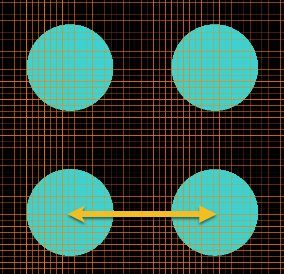
A: If you are referring to the pitch (yellow arrow) between pillars, please have a look at this post. That said, a pitch of λ/10 might be too small to achieve the phase change of 2π through the radius changes. You might also experience strong coupling between neighboring cells at such a small pitch, which makes the whole metalens design quite complicated.

If the question was about the required mesh size (orange lines), λ/10 can be a good starting point to obtain reasonably good accuracy at reasonable speed. But, to be able to trust your simulation results, you need to do a thorough convergence tests.


Q: Are there plans to make the RCWA module more user friendly (GUI, easier layer building) in the future?

A: Yes, a dedicated GUI for RCWA is something we are currently working on. We cannot give a firm dates for its release, though.


I would like to know whether a copy of the Slides from the webinar will become available ? Thank you in advance!  🙂

Yes! Please find the slide deck attached here in pdf format.


Q: What is the rule of thumb in choosing mode number in RCWA? What I meant by “mode number” is “k-vector number.”

A: As with any simulation, this is a matter of convergence. To obtain an accurate result that you can trust, you will need to run a convergence test over the key simulation parameters. The number of k-vectors could be one of the key parameters you want to do the convergence test on in RCWA. If you have a tapered cone in the propagation direction, you will need to approximate the structure with a number of cylinders and also do convergence tests on the number of cylindrical layers to faithfully represent the cone structure.
The number of required k-vectors to obtain a converged result will vary depending on the structures, material and sources you are dealing with.


Q1: Hello, Is it possible to incorporate Ansys HFSS with Zemax?

A1: This will depend on i) what you want to achieve through the combination of the HFSS and Zemax and ii) the type of data exchange required between them. If you can share more details about these, we can provided a more informed comment.

Q2: Also, is it possible to get the slides?

A2: Please see this post for the slides.


@Yisi.Liu 

Q: Metalens can be designed to be polarization-sensitive. How to include such feature in your design process?

A: The Metalens Webinar and the associated Application Gallery example uses a cylindrical meta-atom, hence polarization insensitive. But the proposed design flow can be easily adapted to address the polarization-sensitive devices. The required changes would typically involve:

  • Build the phase and field libraries of unit cell for geometric parameters and the polarization (x- and y-polarized)
  • When reconstructing the field for the whole metalens, construct the field for each polarization.
  • To obtain a response for the whole lens to an input with an arbitrary polarization (a*E_in_x+a*E_in_y), you simply give an appropriate weighting to the whole lens response to each input polarization and sum them (a*E_whole_out_x+b*E_whole_out_y).

Hope this makes sense.


Q: I have question regarding how to convert phase to radius mapping on Lumerical.

A: The working principle of the phase-radius mapping is explained in the “Run and Results » Step 2: Unit cell simulations – Height and radius sweep » Option1: FDTD.” part of the Metalens example.


@Dani.K 

Q1: I would like to ask you if I can design my source in HFSS and then import it to Zemax and how. And how can I change the Y position of my source for example.

A1: Would you please provide more detailed information about i) what you want to achieve with the combined workflow HFSS and Zemax and ii) the source itself (wavelength, the beam shape and how the “source” is defined). With the Webinar being based on the interoperability between Lumerical and Zemax, I wonder what might be the reason behind the use of HFSS in this case. Are you considering taking the workflow learned here and adapt it to something different?

Q2: At the end, I would like to know if it can implement an incoherent detector with a Pixelarray.

A2: Do you have any reference for the application you mentioned? Some sketch of the detector would help us to understand what you might need and whether/how the metalens workflow has any relevance to it.


Reply