This thread is dedicated to the upcoming webinar: Using and Modifying CREO Parts with OpticsBuilder. Any questions received during the webinar will be responded to as a reply on this thread. Feel free to post your own questions! The speaker will be notified and will respond as long as the thread is still open.
Be sure to subscribe to this thread if you want to see additional discussion regarding this webinar topic. The thread will be open to new replies through Friday, June 3rd.
pThe webinar has concluded.]
Webinar details
Date: Thursday, May 26th
Time: 6:00 - 7:00 AM PDT | 11:00 AM - 12:00 PM PDT
Presenter: Flurin Herren, Application Engineer II at Ansys Zemax
Abstract:
In an optomechanical workflow it is quite common that a system needs to be edited during the design process due to added information or changing circumstances. At certain stages of a workflow only specific things can be edited. This requires a tool that can edit more than one specific group of properties at a time. OpticsBuilder is that tool, allowing edits to optical properties such as scattering functions to be made as well as allowing geometrical aspects of parts to be altered. In this webinar, we will demonstrate the various OpticsBuilder features which can be used to do just that.
In this thread below, we answer the questions we didn’t get to during the live event.
If you have any further questions, please feel free to send it here.
@arvid.Lindberg
Q: Is it possible to do tolerance analysis on the mechanical parts to estimate the impact on the optical performance?
A: you may do the tolerance analysis and see the tolerances on the mechanical parts in Creo, and the tolerances on the optical parts using OpticsBuilder (if they were applied in OpticStudio). We are researching tolerance analysis options for the future updates. So, if there is something specific you would like to see, it would be helpful to provide more details so that we can discuss them.
Q: Does OpticsBuilder work with SolidWorks ?
A: As a result of Dassault Systems’ recent decision to conclude Zemax’s membership in the SolidWorks partner program, Zemax is no longer able to support our OpticsBuilder for SolidWorks product. Effective December 31, 2021, SOLIDWORKS integrations with Zemax products were deprecated.
Q: What surface types are supported for export/import? e.g diffractive, freeform, cylinders?
A: A wide rang of surfaces including diffractive, reflective, biconic, freeform, cylindrical surfaces are supported in OpticsBiulder. To prepare for OpticsBuilder, OpticStudio first convert sequential files to non-sequential files. So, these surfaces will automatically be converted into an equivalent non-sequential surface. Some of the supported surfaces include parameters which are not supported in their otherwise equivalent non-sequential surface. If these parameters are used, then the sequential surface will be converted to a non-sequential Grid Sag Surface object. For example, if Zernike terms are used in a sequential Toroidal surface, it will be converted to a non-sequential Grid Sag Surface object. You can read more in this knowledgebase article: Prepare for OpticsBuilder – Knowledgebase (zemax.com)
Q: Can you turn on and off or modify the field angles within optics builder? Or change other standard ZEMAX system parameters from within Optics Builder?
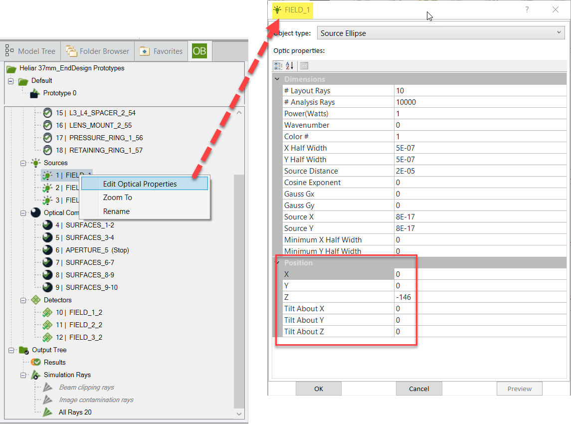
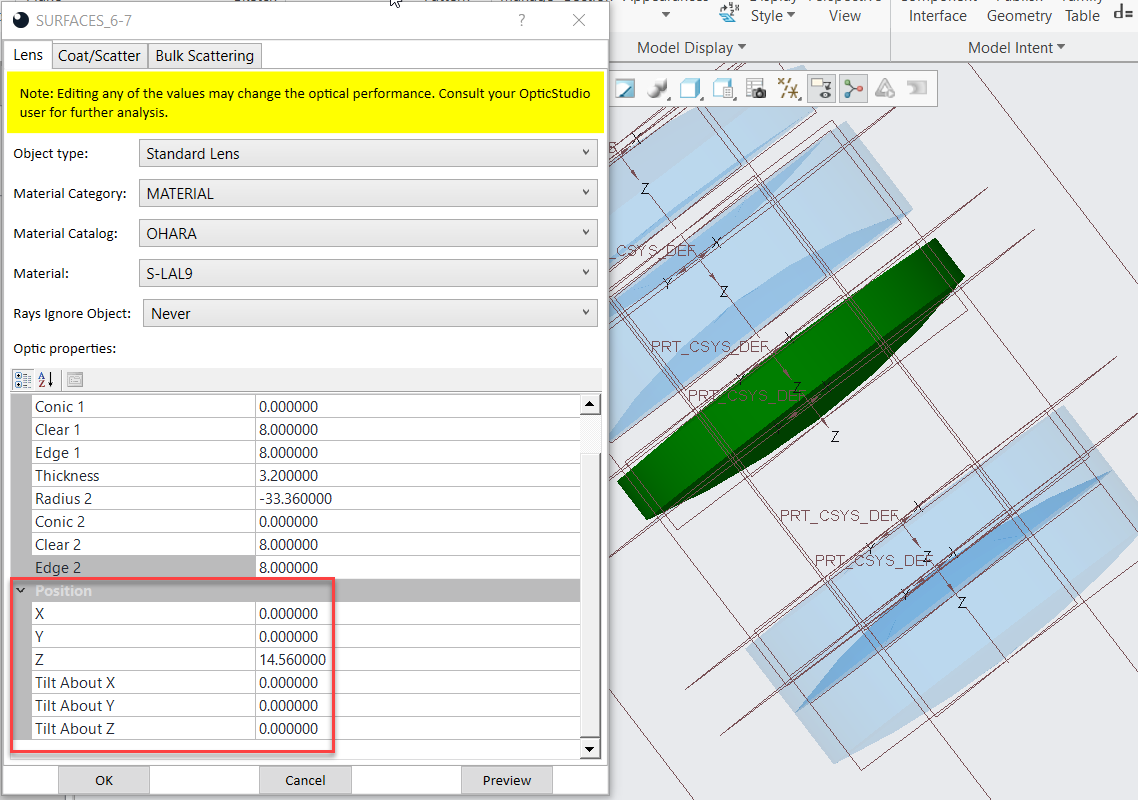
A: You can simply edit the optical properties of the field of interest including its position and orientation by right-clicking on the field in the OB Input Tree and choosing “Edit Optical Properties” as shown below.
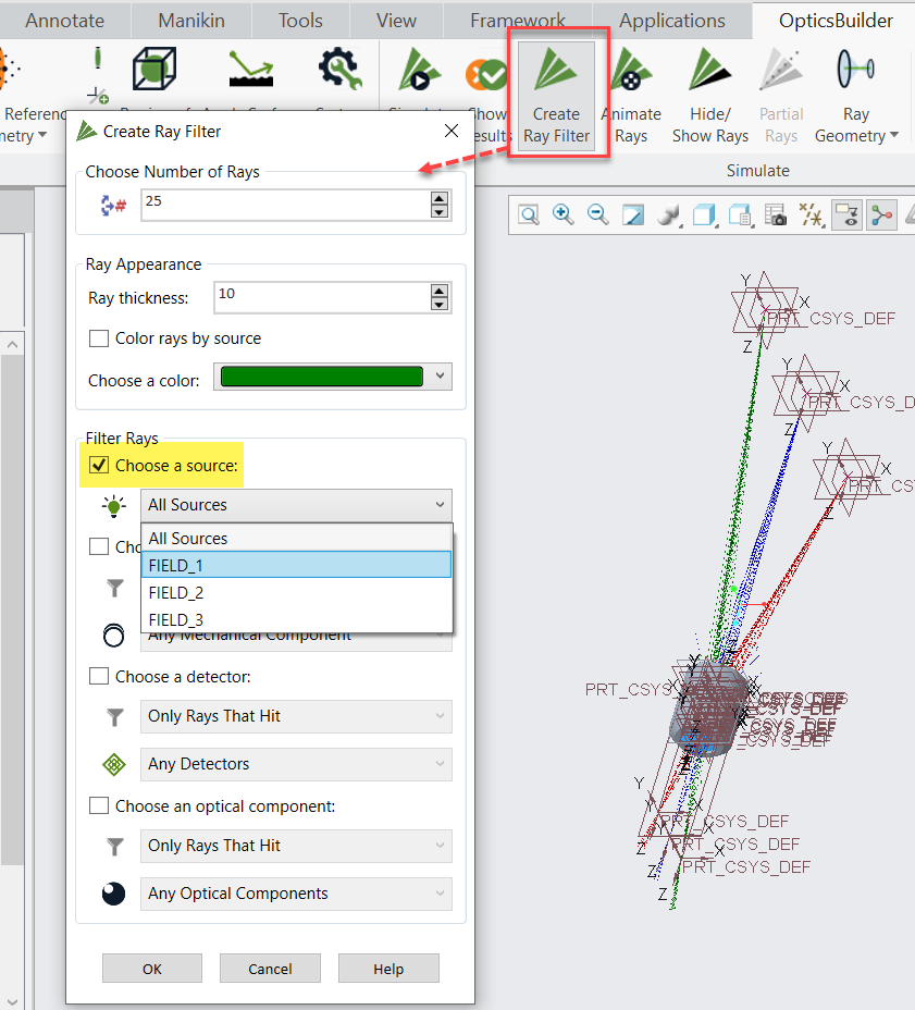
You may also turn a field on or off by creating a ray filter using the “Create Ray Filter” tool:
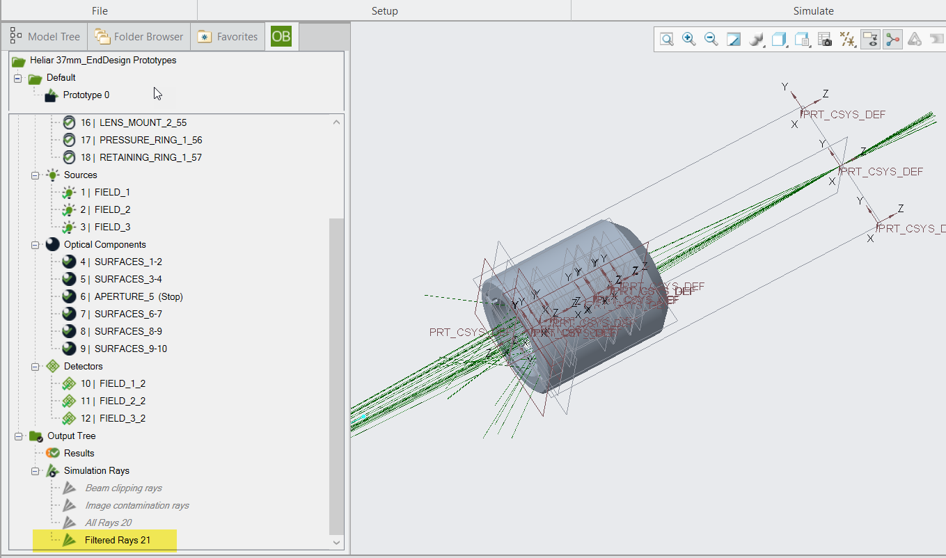
And then through the Output Tree in OB tab you can show or hide the defined ray filter:
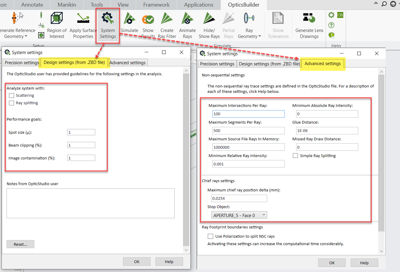
Zemax System parameters can be seen and edited in OpticsBuilder through the “System Settings” tool:
@Neha.Dambhare
Q: Is zemax only use for designing and validation?
A: I wish you could provide more details about your question so that I can give a more specific answer. In general, OpticsBuilder gives the mechanical engineer access to the live optics during the mechanical and optomechanical design. Interoperability between OpticStudio and OpticsBuilder streamlines the design process by effective communication between optical and mechanical designers as they navigate the design changes and real-time visualization of impact on optical performance while designing optomechanics. With OpticsBuilder, CAD users can directly convert complete optical designs from OpticStudio into CAD, analyze how their packaging impacts optical performance, and export optical drawings to manufacturing, saving costs and months of trial and error.
Of course, optimizing and tolerancing your optical system can be done in OpticStudio, and you can simply update your optical design file in OpticsBuilder anytime during the mechanical design.
I missed the webinar unfortunately. I have been trying for several days to view the recording, but I never receive the “confirmation email”. Other Zemax emails are coming though fine, so I don’t think it is blocked by my server.
@Ray
Hi,
If you cannot access the webinar, please reach out to events@zemax.com and ask for the video and the slides, the colleagues at marketing are happy to help you. Please use the specific name of the webinar: Using and Modifying CREO Parts with OpticsBuilder.
Q: Hi Flurin. Thanks for the presentation. I was wondering whether the reverse process could be possible i.e. start from a complete Creo assembly including optical components and then auto-importing it into Zemax. This could be useful as in my example, I have strong mechanical constraints and must adapt the optics to the constrained mechanics. Thank you
A: The optical design needs to be done in OpticStudio. In fact, OpticsBuilder makes it easy for the CAD user to import data from OpticStudio, assess issues in the optomechanical design, and create manufacturing drawings. The Prepare for OpticsBuilder tool is used to package an OpticStudio system into a ZBD file that may be opened in OpticsBuilder. The Prepare for OpticsBuilder feature inside of OpticStudio ensures that all supporting data is grouped with the optical design. The data includes (but is not limited to): the lens material, coatings, source definition, and manufacturing drawing data.
There is an option in OpticsBuilder to load the optical design as a subassembly and “Mate into existing design”. This feature can be used in situations such as your use case by adding an optical system to an already existing mechanical assembly. In OpticsBuilder, you may always edit the properties of the optical components including position and orientation which is a powerful feature to adapt the optics to the constrained mechanics, and assess the impacts on the system optical performance.
@Robin.Hein
Q: Does models need to be started in Optics Studio or can it be created from Creo first? Can OpticsBuilder handle Off Axis mirrors?
A: For the first part of the question, please see the previous post.
As for the second question, the answer would be yes, the Off-axis mirror object is supported in OpticsBuilder.
Q: Are you able to share this presentation?
A: Allie has posted the link to a recording of the webinar on top of this thread. For the presentation slides, please reach out to events@zemax.com . Our colleagues at marketing are happy to help you.