

Nonsequential mode is designed to quickly trace millions of rays through complex geometries. But for the setup or initial optimizations of systems, it is sometimes useful to trace and optimize just a few important rays. One can use the NSTR operand and the Source Ray objects to do this. The process requires some manual setup, but can easily be automated using the ZOS-API.
As an example, I have a system that contains a plate and an off-axis parabola (OAP). I’ve manually moved the detector, but I would like it to be centered on the gut ray and tilted to find the image.
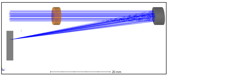
In the Nonsequential Component Editor (NCE), I’ve added 9 Source Ray objects. I’m separating them in the Y direction, at field points of 0, 0.2° in +Y, and 0.2° in +X. Each set of three rays that have the same field angle should come to a focus in the image plane, as shown in the layout plot below.
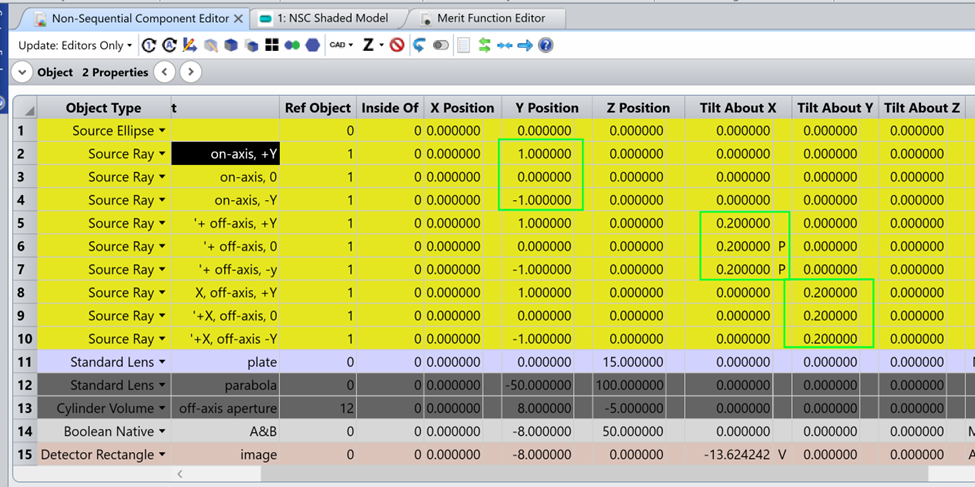
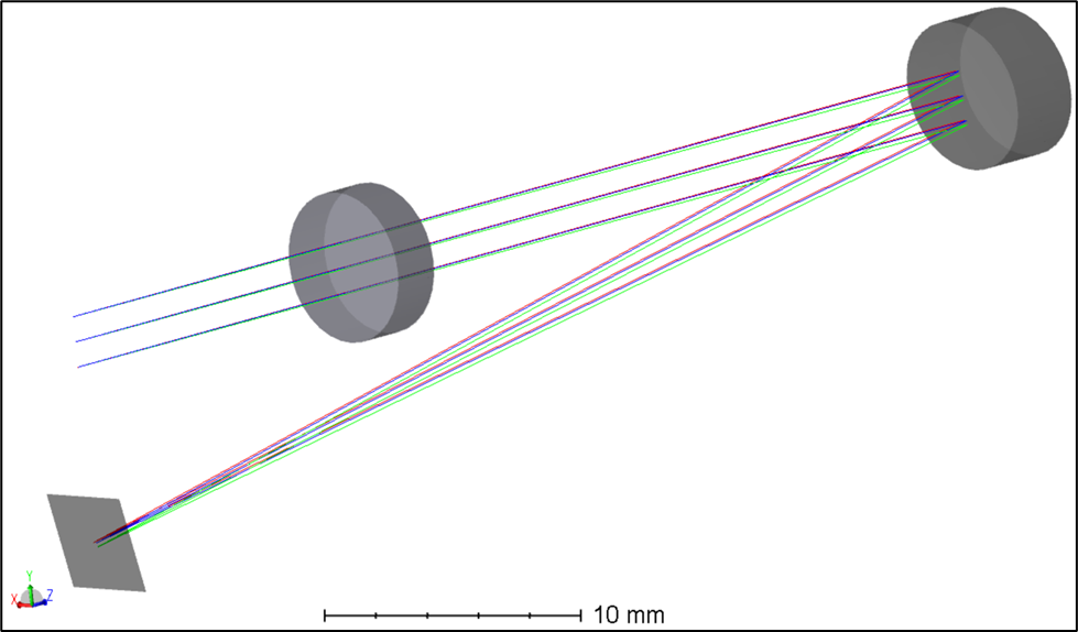
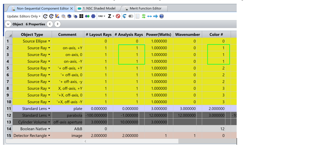
I color-coded the rays using the Color # column so that rays that should meet in the image plane have the same color. I also set the number of layout and analysis rays to 1. I also set the number of rays to 0 for any other sources in the system.
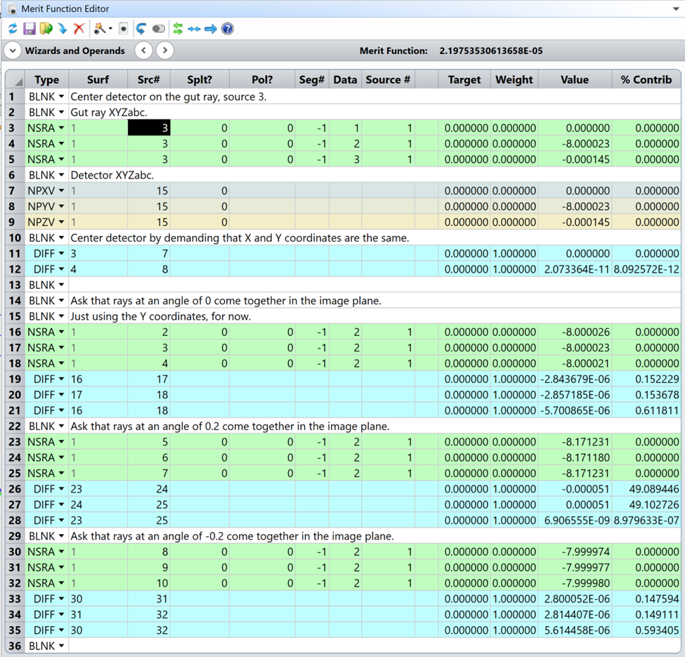
Now, in the Merit Function, I can use NSRA to return data about these rays. Data values 1, 2, and 3 return the X, Y, and Z coordinates of the ray. I use Seg# = -1 to find the last segment of the raytrace before the ray is terminated. And I’ve left splitting and polarization off so that I get the straight-through ray path.
In the Merit Function shown below, I use lines 11 and 12 to demand that the detector position is centered on the gut ray. In rows 19-21, I ask that the on-axis rays have the same Y coordinates in the detector plane. (One could do the same for the X coordinates, but I’ve simplified here.) And rows 26-28 and 33-35 demand that the rays come together for the off-axis angles.
In the NCE, I’ll set the detector’s Y position, Z position, and Tilt About X to be variables. (For a full 3D optimization, I would also use the Tilt About Y and X position.)
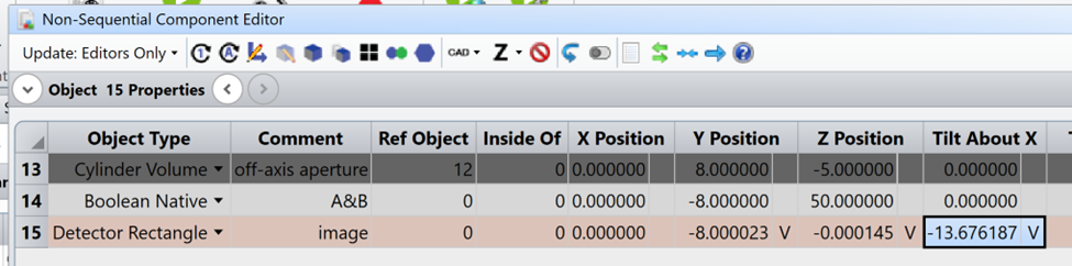
And finally, I can optimize to find the detector position. The final values are shown above.
A few notes:
- Note that for the detector, I’ve kept the number of pixels in X and Y equal to 1, just for a little extra speed.
- There are some potential pitfalls with this technique. If the ray doesn’t hit the detector, so that the last segment has an unexpected location, things can quickly go awry. If the system is changing significantly during an optimization, you might find that the ray is landing on the wrong object.
- Technically, because of where I’ve launched the rays, I’ve defined a pupil in the plane where the rays launch. That’s because the rays at the same pupil height but different field angles leave from the same location. In this case, that won’t affect the results much. But ideally, you should locate the entrance pupil of the system and launch the rays from there. See this forum post on placing a surface at the entrance pupil: