Tech Tip Tuesday: Working with freeform HUD elements

  • 30 November 2021
  • 5 replies
  • 774 views

Userlevel 2
Badge

In a previous Tech Tip Tuesday we discussed some of the analyses available in OpticStudio to evaluate systems with freeform surfaces. For this Tech Tip Tuesday – HUD Edition: We will discuss tools available to aid with the import, conversion, and/or fitting of pre-existing freeform elements in OpticStudio.


In modern Head-Up Display systems, the optical designer is often required to incorporate some flavor of pre-existing, freeform optical element. The pre-existing element could be an airplane canopy, off-the-shelf combiner element, an automotive windshield, etc. The native data formatting of this freeform element varies by both industry application and by individual design team preference. These surfaces may have natively been created and stored as CAD files, an extended polynomial, or even just a sampled sag table. For any of these cases, OpticStudio has the answer!

  • Import STEP/IGES/SAT/STL files directly
    • OpticStudio is able to directly import STEP, IGES, SAT, and STL file types into Non-Sequential Mode and Mixed Mode without any loss in precision from the original CAD export.
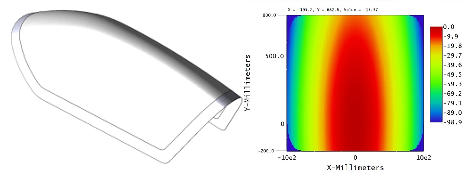
  • Convert imported CAD files to Grid Sag surfaces
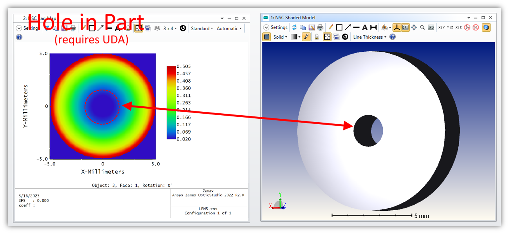
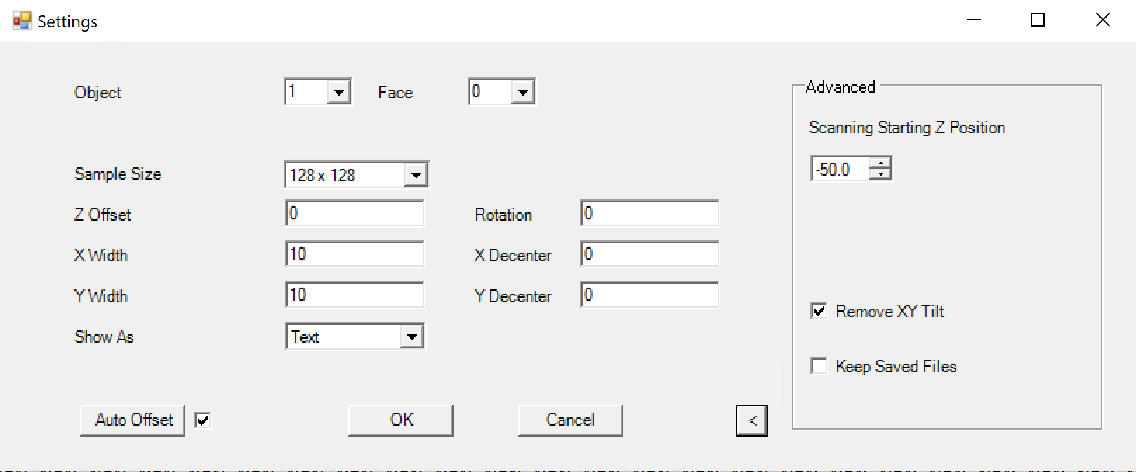
    • The Non-Sequential Sag Mapping Tool can be used to generate a sag table and plot for each of the imported CAD surfaces of interest. These sag tables can now be imported into sequential mode as Grid Sag surfaces!
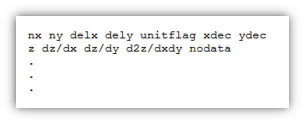
      • OpticStudio automatically applies a bi-cubic spline fit to the tabulated data in the Grid Sag Surface file
      • This freeform surface is now optimizable via the “Grid Point Optimizer”
  •  The “Convert Asphere” tool allows the designer to convert a Grid Sag surface to an Even, Extended, Q-Type 0, or Q-Type 1 aspheric surface.
    • The freeform surface is now parametrized
    • The freeform surface is now optimizable with all optimizers in OpticStudio


5 replies

Userlevel 6
Badge +2

Hey Everyone,

The statement of “These sag tables can now be imported into sequential mode as Grid Sag surfaces” means that you have to manually convert the 2D XY values (when you select Show As to Text) and then loop through (either with a ZPL or a Python/Matlab script) to convert the XY value to the .DAT Grid Sag format.  The Grid Sag format is:

The main reason this isn’t included by default in the tool is anything released by Zemax should work in 100% of cases.  However, if you have even a simple geometry like below with a hole in the part, this becomes extremely difficult to implement in sequential mode:

You would need to:

  • Create a User-Defined Aperture to block rays in the hole (a Grid Sag will just model this a 0 sag but the rays will still “enter” the part).  
    • For a circle this is relatively easy but for an arbitrary shape this becomes extremely difficult (edge detection algorithm with a convex hull implement to test inside/outside boundaries)
  • If you want to properly model rays that go through the hole, then you would need to create multiple configurations:
    • one with the UDA to block the rays
    • one with a User Defined Obscurration to block rays that “hit” the part but transmit through the hole). 
  • Then you would need to find a specific analysis that allows you to combine multi-config (Geometric Image Analysis, Huygens PSF/MTF or a custom ZOS-API analysis)

So for those users who can simply convert the XY output to a Grid Sag, they can use their own scripts but in general unless Zemax can find a universal solution for all users, I doubt they will implement a Grid Sag export anytime soon.

Hi Kerry,

Thanks for the article. I’m excited by this feature.

One step I got stuck on is your 2nd bullet point where the surface is supposed to be saved in “Grid Sag” format in the NSC sag mapping tool. I did not see an option to specify “Grid Sag” in my settings file (shown below). My understanding was grid sag surface in sequential mode is imported using .dat file, but this format only saved .txt format. Is there something I missed in my conversion to get .dat format?

Thanks in advance!


I also didn't find a dat file that could be used directly. My solution was to take out the array data in txt and then use python to write the data into dat file, which was relatively troublesome. Perhaps saving directly to dat is a new feature of ZEMAX later on?

Hi Kerry,

Would you please share more details on how to import the ZRD file (exported from Non-Seq Sag mapping tool) into the Sequential Mode surface? 

I have the same question.  Can we get more information on how to import? Thanks

Hi Kerry,

Thanks for the article. I’m excited by this feature.

One step I got stuck on is your 2nd bullet point where the surface is supposed to be saved in “Grid Sag” format in the NSC sag mapping tool. I did not see an option to specify “Grid Sag” in my settings file (shown below). My understanding was grid sag surface in sequential mode is imported using .dat file, but this format only saved .txt format. Is there something I missed in my conversion to get .dat format?

Thanks in advance!


Reply