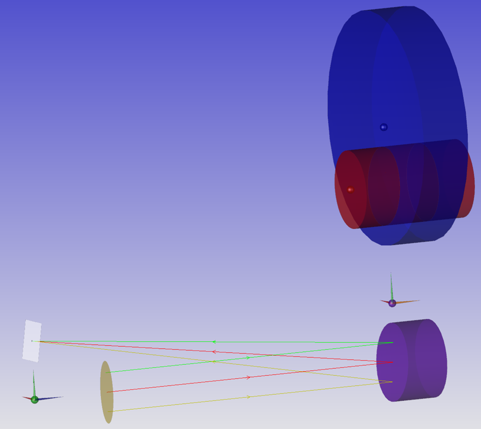
Objects in nonsequential mode can be used as reference points, and set so that they don’t interact with the rays. This is useful for setting up folded systems, Boolean objects that are combinations of other objects, and systems with CAD parts referenced to a mechanical coordinate system. Also, Source Rays can be used with optimization to automatically position parts along a gut ray.

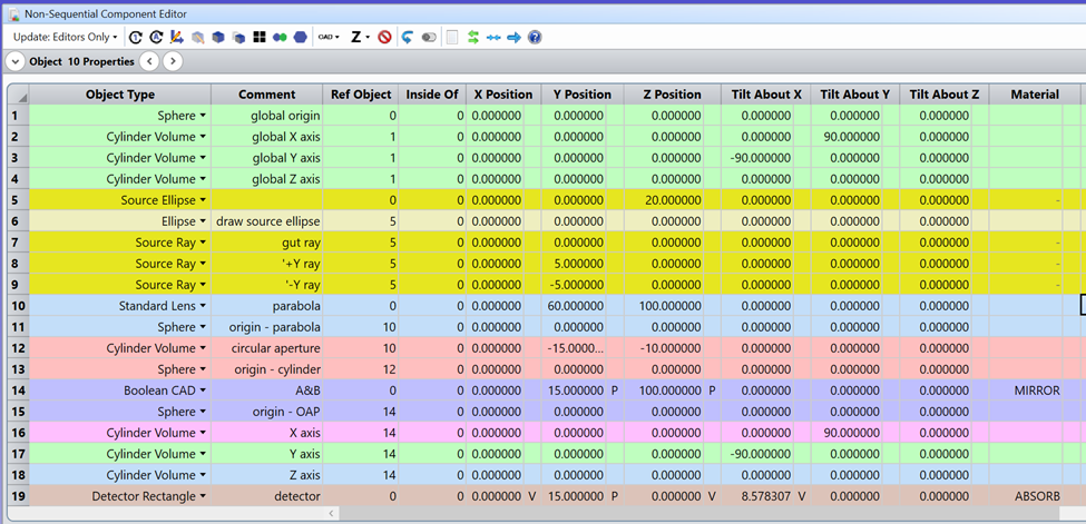
I’ve created an off-axis parabola (OAP) file that illustrates those techniques. The mirror is a Boolean combination of two objects: a parabolic “lens” and a cylinder volume. I’ve placed spheres at the origin of each part by referencing the Sphere to its object in the Ref. Object column of the Nonsequential Component Editor (NSCE). I’ve also color-coded rows and objects to display in the same color using,
Properties / Type / Row Color and Properties / Draw / Object Color.

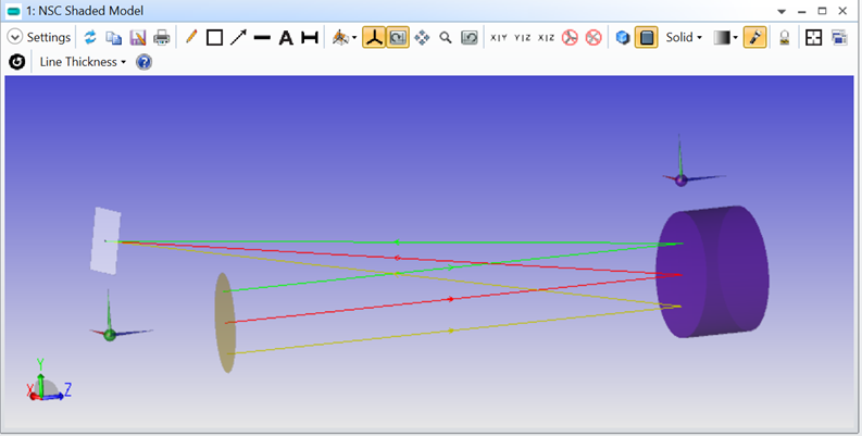
I can clean up the NSCE and the Shaded Model by:
- Setting Properties / Type / Raytrace / Rays Ignore Object = Always, to insure that no materials, coatings, or scattering properties on the object could affect the rays,
- Checking Properties / Draw / Do Not Draw Object,
- Right-click to hide rows with unused objects.


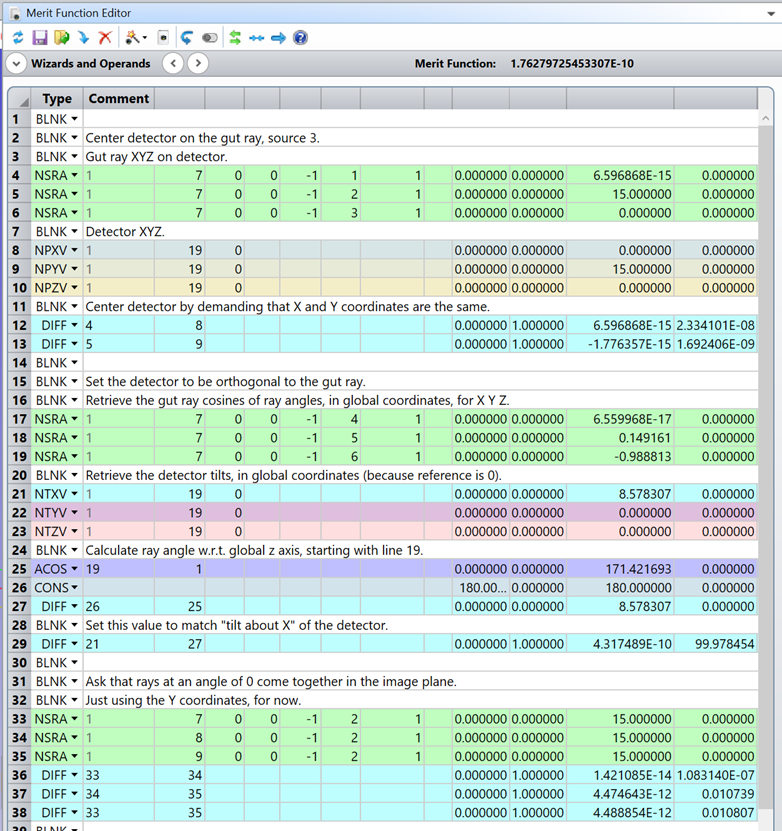
I’ve added three Source Rays (rows 7 – 9), and used them to position the detector by demanding that the rays overlap at the detector and that the detector is orthogonal to the gut ray. The Merit Function used is shown below. NSRA returns XYZ and direction cosines for the Source Rays. NPXV, NPYV, and NPZV return the detector coordinates in the global coordinate system, and NTXV, NTYV, and NTZV return the direction cosines of an object. This example was set up in the YZ plane, but extending this to three dimensions is possible.


