This is a brief description of my recent experience using POP to model diffractive optical elements that may be of some interest to other users.
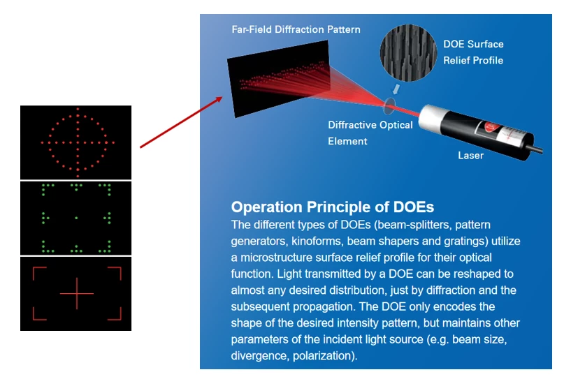
It is well-known that Diffractive Optical Element (DOE) technology can be used to generate custom intensity patterns or images based on coherent optics. For example, illumination of properly constructed phase elements (i.e., DOEs) by a coherent laser beam can produce interesting intensity patterns in the far field. Anyone who has walked the exhibit hall at Photonics West has surely seen examples of this. Various techniques can be employed to design a DOE, with the Iterative Fourier Transform Algorithm being one popular scheme (see, e.g., F. Wyrowski and O. Bryngdahl, “Iterative Fourier-Transform algorithm applied to computer holography,” JOSA-A 1988).
Here is a brief description taken from the Holoeye website:

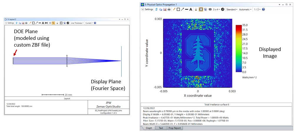
Modeling DOEs in OpticStudio is possible by using Physical Optics Propagation (POP). One can envision two possible approaches: (1) model a phase-only DOE by using a Grid Phase or Grid Sag surface, or (2) mimic the output of the DOE by constructing a custom ZBF file to use as the source field. I find the first approach is subject to a few potential problems, while the second approach seems to work quite nicely. Some details associated with the first approach (Grid Phase/Sag surface) can be found here:
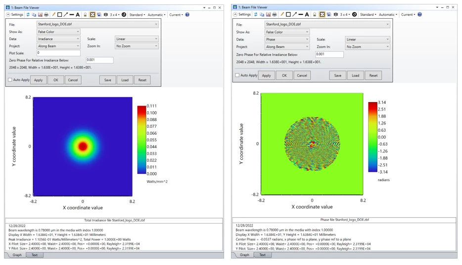
Here’s an example of the second approach based on a ZBF source file that defines a beam leaving the front focal plane of a lens (where the DOE is assumed to be located), and propagating to the back focal plane where the Fourier transform of the source field is found. The complex field defined by the ZBF file has a Gaussian intensity profile and a phase distribution calculated to produce the Stanford University logo in the Fourier plane.


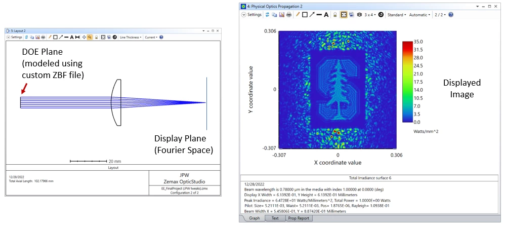
If the paraxial lens is replaced by a simple plano-convex lens, a degradation of the image quality due to spherical aberration is observed.

Presumably more complicated optical paths, such as for near-eye display, or perhaps a path that includes spatial filtering, can also be simulated.
Regards,
Jeff


