Modeling DOE Pattern/Image Generation using POP

  • 29 December 2022
  • 7 replies
  • 879 views

Userlevel 7
Badge +3

This is a brief description of my recent experience using POP to model diffractive optical elements that may be of some interest to other users.

It is well-known that Diffractive Optical Element (DOE) technology can be used to generate custom intensity patterns or images based on coherent optics.  For example, illumination of properly constructed phase elements (i.e., DOEs) by a coherent laser beam can produce interesting intensity patterns in the far field.  Anyone who has walked the exhibit hall at Photonics West has surely seen examples of this.  Various techniques can be employed to design a DOE, with the Iterative Fourier Transform Algorithm being one popular scheme (see, e.g., F. Wyrowski and O. Bryngdahl, “Iterative Fourier-Transform algorithm applied to computer holography,” JOSA-A 1988).

Here is a brief description taken from the Holoeye website:


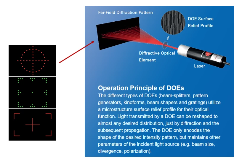
Modeling DOEs in OpticStudio is possible by using Physical Optics Propagation (POP).  One can envision two possible approaches: (1) model a phase-only DOE by using a Grid Phase or Grid Sag surface, or (2) mimic the output of the DOE by constructing a custom ZBF file to use as the source field.  I find the first approach is subject to a few potential problems, while the second approach seems to work quite nicely.  Some details associated with the first approach (Grid Phase/Sag surface) can be found here:


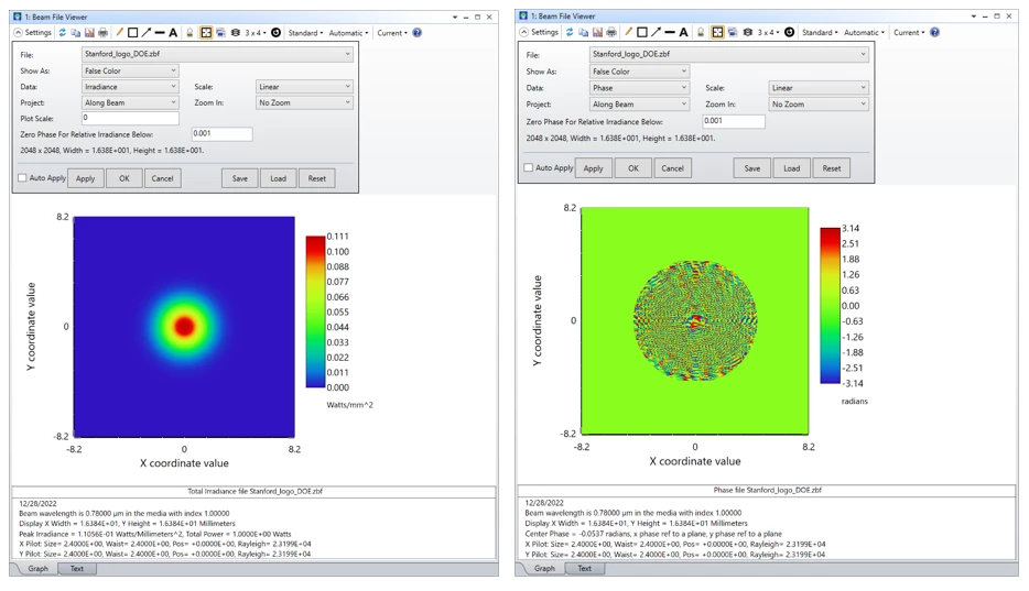
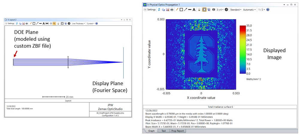
Here’s an example of the second approach based on a ZBF source file that defines a beam leaving the front focal plane of a lens (where the DOE is assumed to be located), and propagating to the back focal plane where the Fourier transform of the source field is found.  The complex field defined by the ZBF file has a Gaussian intensity profile and a phase distribution calculated to produce the Stanford University logo in the Fourier plane.


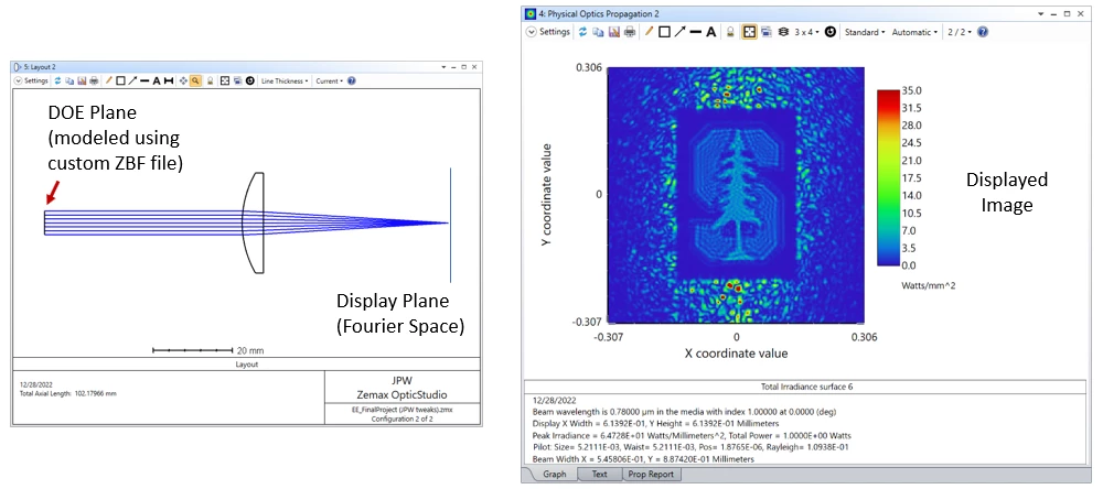
If the paraxial lens is replaced by a simple plano-convex lens, a degradation of the image quality due to spherical aberration is observed.


Presumably more complicated optical paths, such as for near-eye display, or perhaps a path that includes spatial filtering, can also be simulated.

Regards,

Jeff


7 replies

Hi Jeff, 

Thank you for sharing your simulation and information. If we want to use the phase light modulator in an optical setup which means the beams are reflected by PLM, can still we use ZBF for CGH simulation?

Userlevel 7
Badge +3

Hi Shay,

Yes, the ZBF file allows you to define the optical field leaving the the SLM/CGH for either transmissive or reflective devices.  If aberrations of the illumination beam are important, they would need to be included in the ZBF file, or you could consider using the Grid Phase approach with the incident field defined by propagation through the prior surfaces.

Regards,

Jeff

Userlevel 7
Badge +3

Hey @Jeff.Wilde , have you used the Optically Fabricated Hologram to create the phase masks at all?

Thanks for your answer. Could you please share your .zbf file? 

Userlevel 7
Badge +3

@Shay :  Unfortunately I’m not at liberty to share the ZBF file because it was created by a student as part of their final project.  However, the help guide describes the available file format options.  You can first try something simple, like a quadratic phase function to mimic a weak thin lens, then once working, go for a more complicated pattern.

Userlevel 7
Badge +3

Hi @Mark.Nicholson:  In the past I’ve used the optically fabricated hologram to model, well... an optically fabricated hologram -- in which the recording medium only responds to intensity, so a fringe pattern is required to capture the phase.  However, with an SLM, a complex pixelated pattern (transmittance or reflectance) can be directly displayed.  So for CGH/DOE purposes, the user typically just programs the pattern so that uniform illumination by a coherent plane wave produces the desired complex optical field leaving the SLM (no fringe pattern required; the SLM pattern is directly imprinted onto the plane wave).

Hi @Jeff.Wilde I am wondering what would be the option to simulate the SLM or other pixelated phase delay surfaces considering the pixilation into account as well (simulating according to the dimensions of the each phase delay pixel). Do you think considering this in Zemax is possible? or maybe due to the calculation method in zemax it is not going to have a significant impact on the results?

Thanks,

Sina

Reply