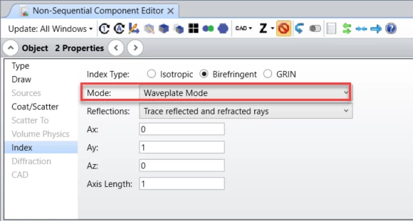
In order to properly model the polarization rotation of an object made of birefringent material, we have to set up the ray trace mode of the object in the Non-Sequential Component Editor under Object Properties > Index > Birefringent type > Mode:

The Mode control allows selection of which rays are actually traced. The distribution of energy does not change with this setting, and energy assigned to rays that are not traced are placed in the “lost energy (thresholds)” sum. Either ordinary or extraordinary rays, or both, may be traced. Waveplate Mode traces the energy along the path of the ordinary ray, however, the extraordinary electric field is also propagated with the ray, and the total electric field will be phase rotated by the differential index in the ordinary and extraordinary directions.
Waveplate mode has to be used to model the polarization rotation of the object.
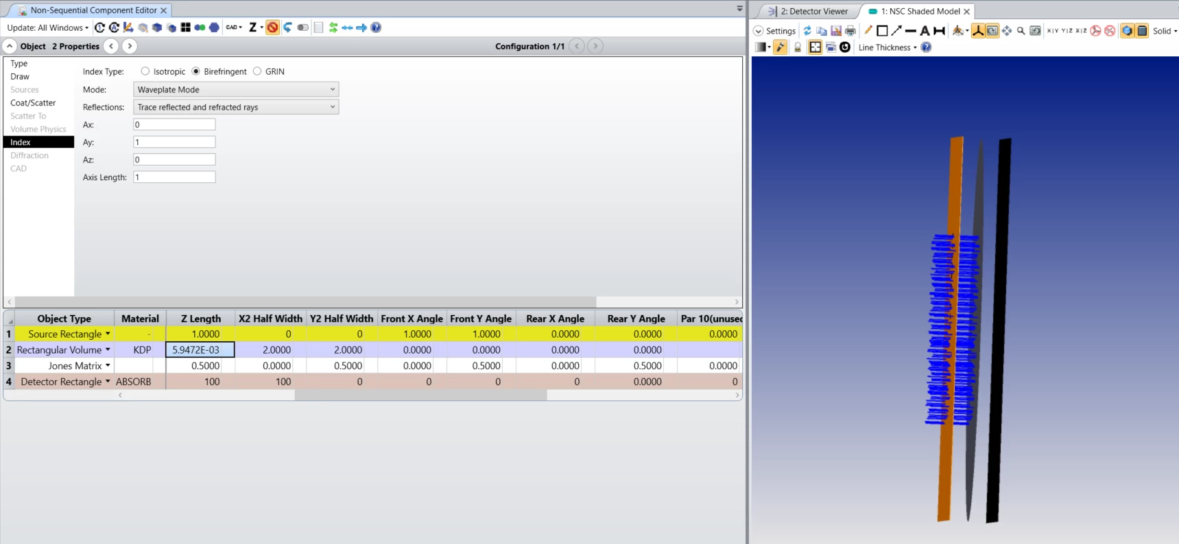
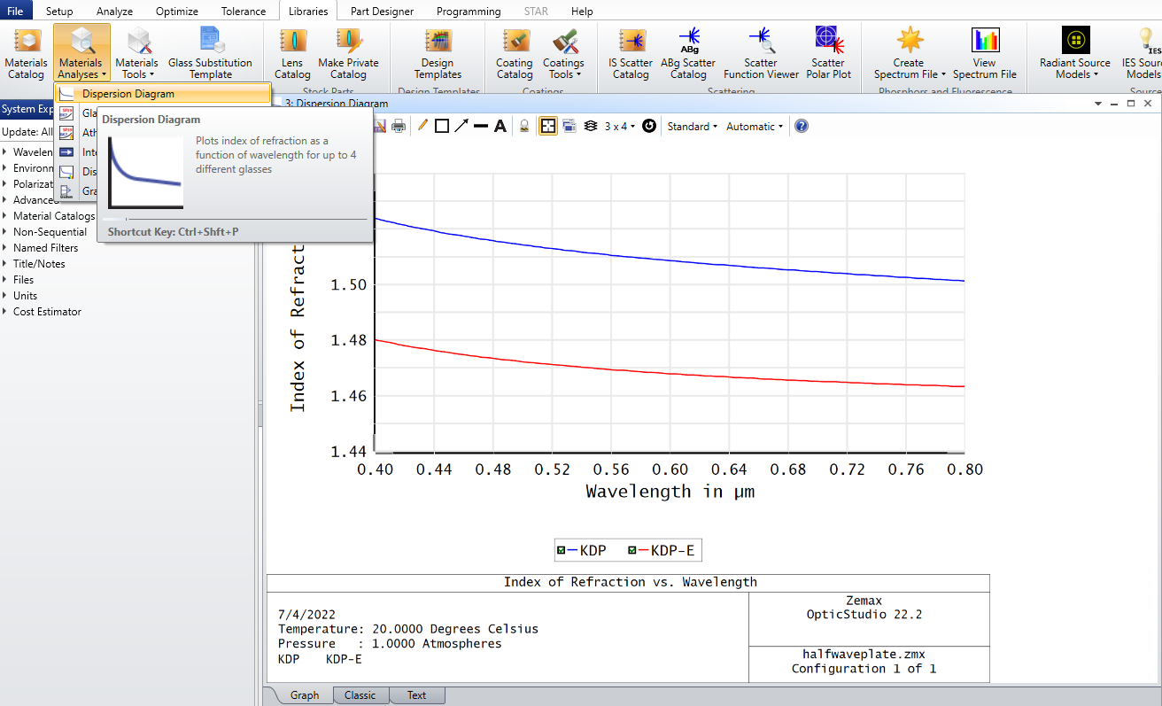
In the attached example file, an extended source (Source Rectangle) launches rays parallel to the z-axis with polarization [1, 1]. Then, a Rectangular Volume with birefringent material KDP is used as a half-wave plate -- the thickness of the object is set up, so that the optical path difference between the ordinary and the extraordinary rays equals the half of the wavelength. The half-wave plate rotates the polarization by 90 degrees. Finally, a Jones matrix object is used to check the resulting polarization -- it is set to transmit polarization parallel to the source polarization, so it blocks all the rays:

Further information about the Birefringent Types settings can be found in the Help file at:
The Setup Tab > Editors Group (Setup Tab) > Non-sequential Component Editor > Object Properties (non-sequential component editor) > Index > Birefringent Types


