Find the exit pupil using real rays

  • 2 February 2024
  • 3 replies
  • 115 views

Userlevel 4
Badge +1

Hi, everyone.  Often, we need to control the size and location of the exit pupil in an optical design so that filters or other elements can be placed there.  It’s fairly easy to place a dummy surface at the exit pupil and then use operands on thickness, diameter, or global position to control the exit pupil location and size.

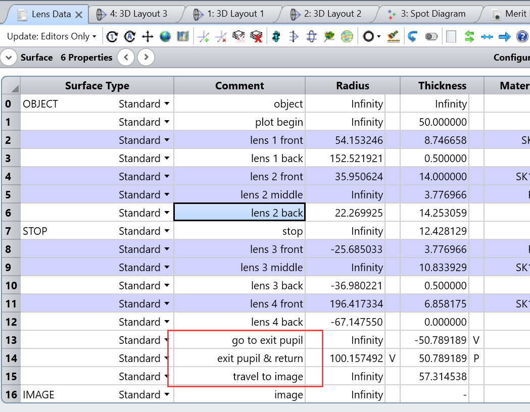
For the Double Gauss system below, I’ve added two surfaces at rows 13 and 14: one going to the exit pupil, and one returning to the original position using a pickup.  Surface 14 will be located at the exit pupil, then.  I’ve also moved the original thickness traveled to the image plane down to surface 15, preceding the image plane.
 

Additional surfaces inserted so that surface 14 can be optimized to fall at the exit pupil.

To move the dummy surface to the exit pupil, I rely on the fact that rays that intersect at the stop should also intersect (or nearly so) at the exit pupil.  To find the Z location of the exit pupil at wavelength 2 for the on-axis field position, I choose rays at 0 pupil height that are separated by small field angles.  Here I’ve used field angles in Y, but one could use a cone of rays for more accuracy.  I also set the thickness of surface 13 to be a variable.  

A merit function that requires rays at a small angle to come together at the exit pupil.

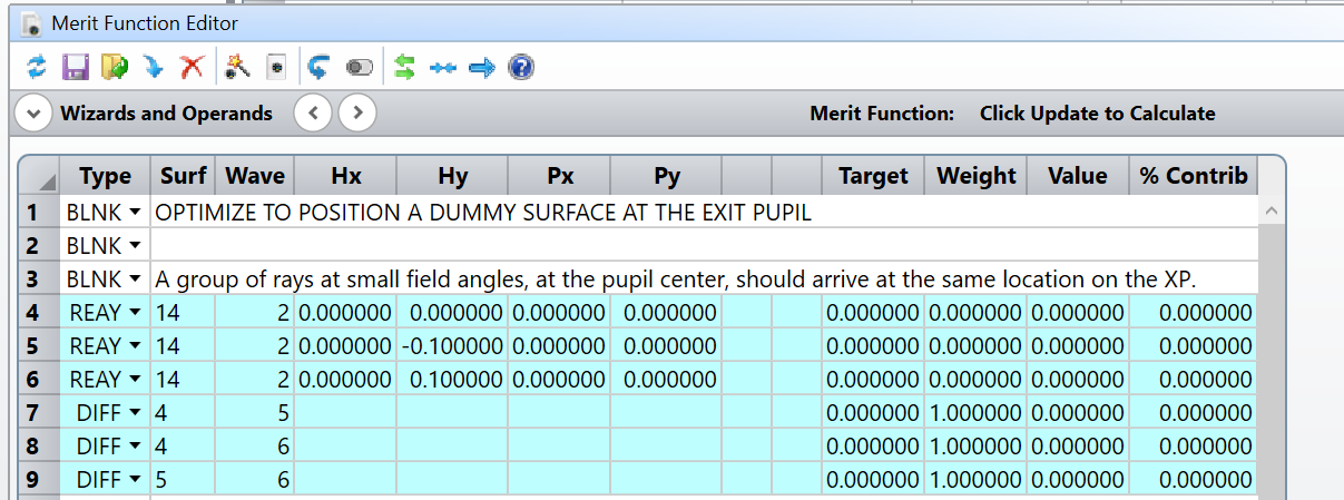
(I can add additional groups of rays at other heights in the pupil, if I want to also find the tilt and curvature of the pupil.)

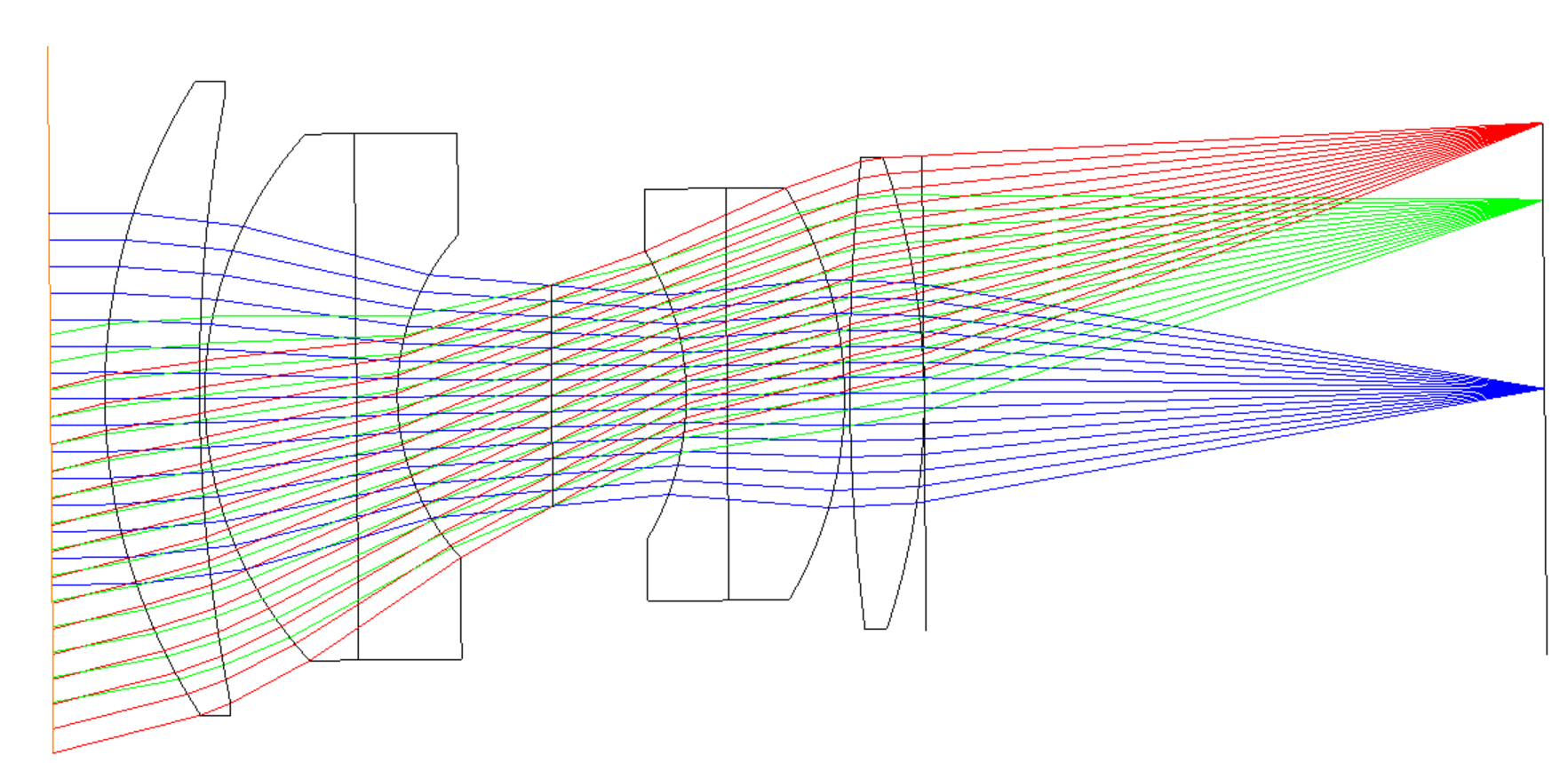
Plotting the design with multiple field angles clearly shows the stop at the center of the system.  And after optimization, the the on-axis exit pupil is about 108 mm behind the image plane.  Surface 14 can now be used to control the exit pupil diameter and location.
 

The stop at the center of the system.
The exit pupil of the system, at surface 14, is located about 157 mm back from the image plane.

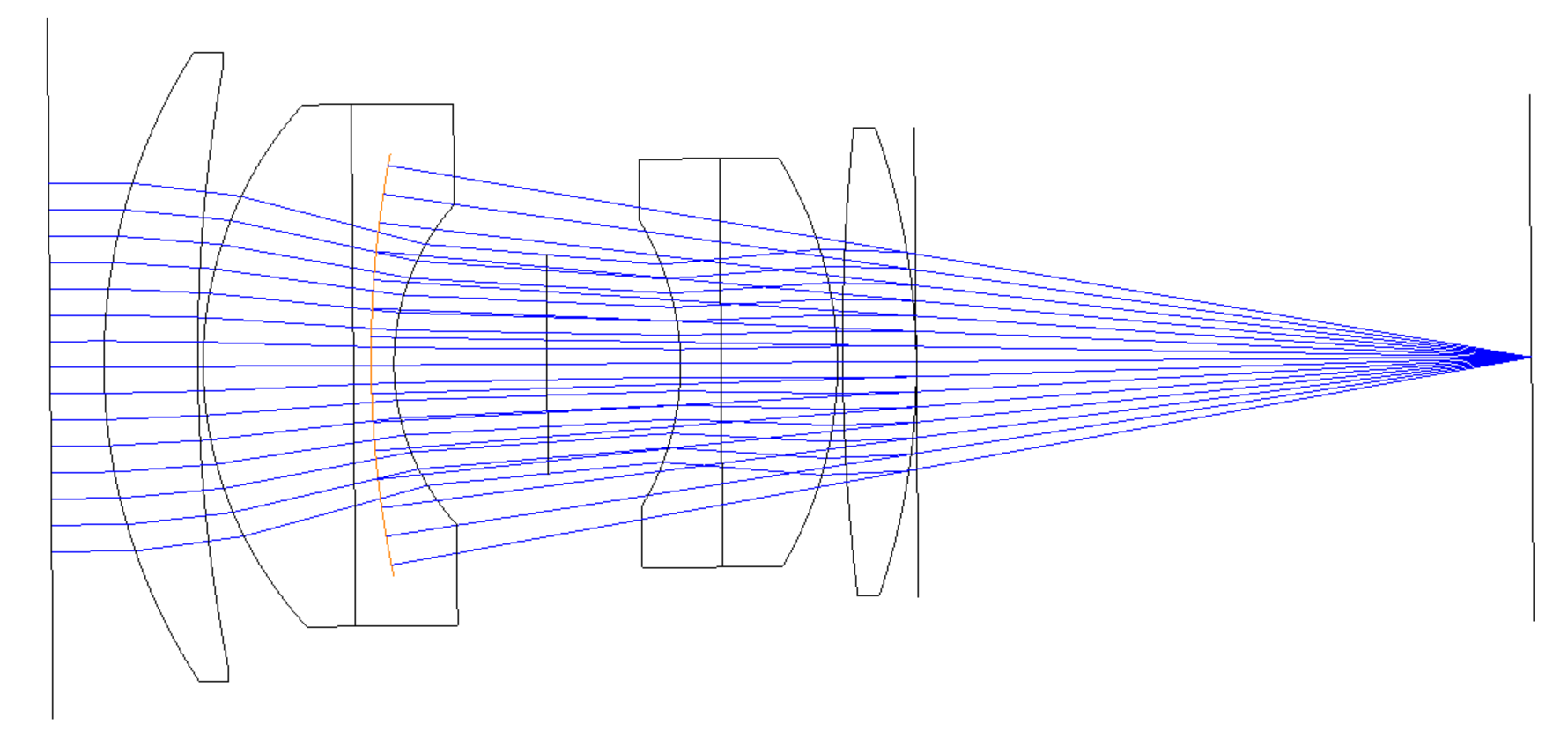
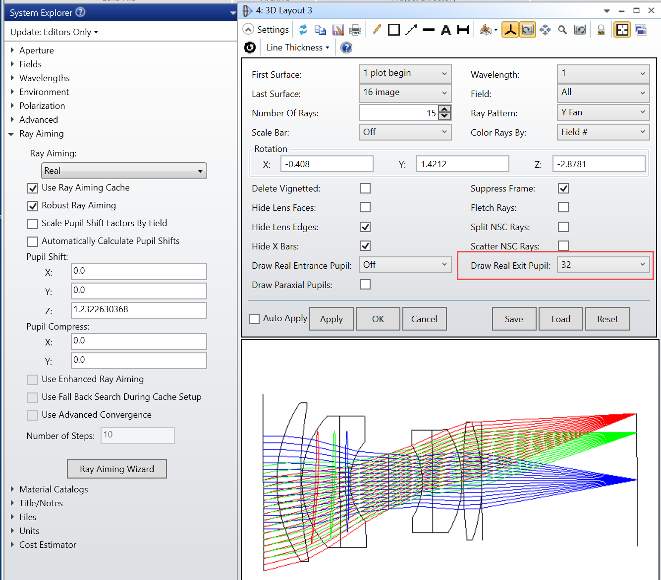
A few additional notes:  The exit pupil typically moves as a function of field angle.  You can see this effect by turning ray aiming on and choosing “Draw Real Exit Pupil” in the layout plots, as shown below. (This is a real effect; if you peer backward into a camera lens and move the lens in X and Y, the exit pupil will move around in space.)

Also, locating the pupil can be inexact, because the pupil image may be blurred; the rays selected in the Merit Function may not come together perfectly.  (This is also a real effect; if you peer into a camera lens you will see the exit pupil but it likely will not be in sharp focus.)  The rays overlap perfectly only at the stop itself.
 

Movement of the exit pupil as a function of field angle, using the “Draw Real Exit Pupil” option.


3 replies

Userlevel 6
Badge +2

Hey Erin, 

Really cool post.  A point of clarification with the below quote:

the the on-axis exit pupil is about 157 mm behind the image plane.  Surface 14 can now be used to control the exit pupil diameter and location

I believe the Exit Pupil should be 107mm behind the image plane (not 157mm).  Also, maybe make it explicitly clear that Surface 14 controls the exit pupil diameter and Surface 13 controls the exit pupil location.

I haven’t played around with the 24.1 release so I haven’t been able to use the Draw Real Exit Pupil, but it looks like the layout is connecting the Top & Bottom points which makes it a little confusing, but the blue on-axis Exit Pupil looks like it is at the same location and diameter as the Dummy Surface 14, but the curvature looks slightly off (the Dummy Surface actually looks more curved).  And then looking at the 14deg red Exit Pupil, it actually looks convex rather than concave rather than convex.  Is this expected?

Did OpticStudio change anything about the diffraction calculations in 24.1 to reflect “real” exit pupils or is the reference sphere OPD calculation unchanged?  


Userlevel 7
Badge +3

This is great Erin. Could you do a follow-up with one of the wide angle lens sample files? I’d do this myself, but my license does not support this feature.

The movement of the pupil is the key feature that makes a lens ‘wide angle’

  • Mark


Userlevel 4
Badge +1

Mark - Will do!  The pupil visualization is really useful for wide fields.

Michael - No change to the diffraction calculations, which tend to use the on-axis paraxial vertex as the reference for wavefront, PSF, etc.

- The "Draw Real Exit Pupil" feature uses a more sophisticated algorithm than the simple one I've shown here; it will be more accurate than my version.

- The "Draw Real Exit Pupil" feature lets the user choose the number of segments.  In the images above, I've got 32 segments that outline the edge of the exit pupil.

A fun tidbit... pupil aberrations are interesting in themselves, of course.  I like the UofAZ/Shack polynomials for this, Wkmn because they include Field.  For the pupil, all the same aberrations can occur, except H → P and P → H.(!)

Reply