FAQ of Optically Fabricated Hologram (OFH): how to parameters Holo type and Diffract order

  • 5 June 2020
  • 8 replies
  • 1079 views

Userlevel 6
Badge +2

Here is a quick note about two frequently asked questions.

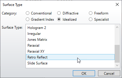
  1. How to set up the parameter Holo type and Diffract order for the surface Optically Fabricated Hologram (OFH)
  2. How to set up a reflection hologram using OFH

Before read this post, make sure you have read the following KBA. That is the background knowledge to this post:
How to model holograms in OpticStudio

Ā 

Difference between OFH and other hologram type

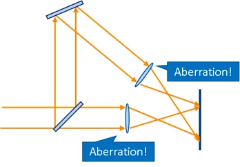
For other hologram models, we only assume the construction systems are composed by two converging or diverging source. (A collimated source is considered as case the converge/diverge point is at far point.)

Ā 

Ā 

200605-225513-image.png

However, in real world, they are built with same laser with some lenses. And there the source is actually not a point but has some aberrations. Sometimes these aberrations are intentionally introduced to correct the aberrations that comeĀ in playbackĀ systems.

Ā 

200605-225548-image.png

Ā 

Ā 

The parameter 'Holo type'

For OFH, the rule for Holo type is a little different compared to other hologram models. Normally, the Holo type should 1.
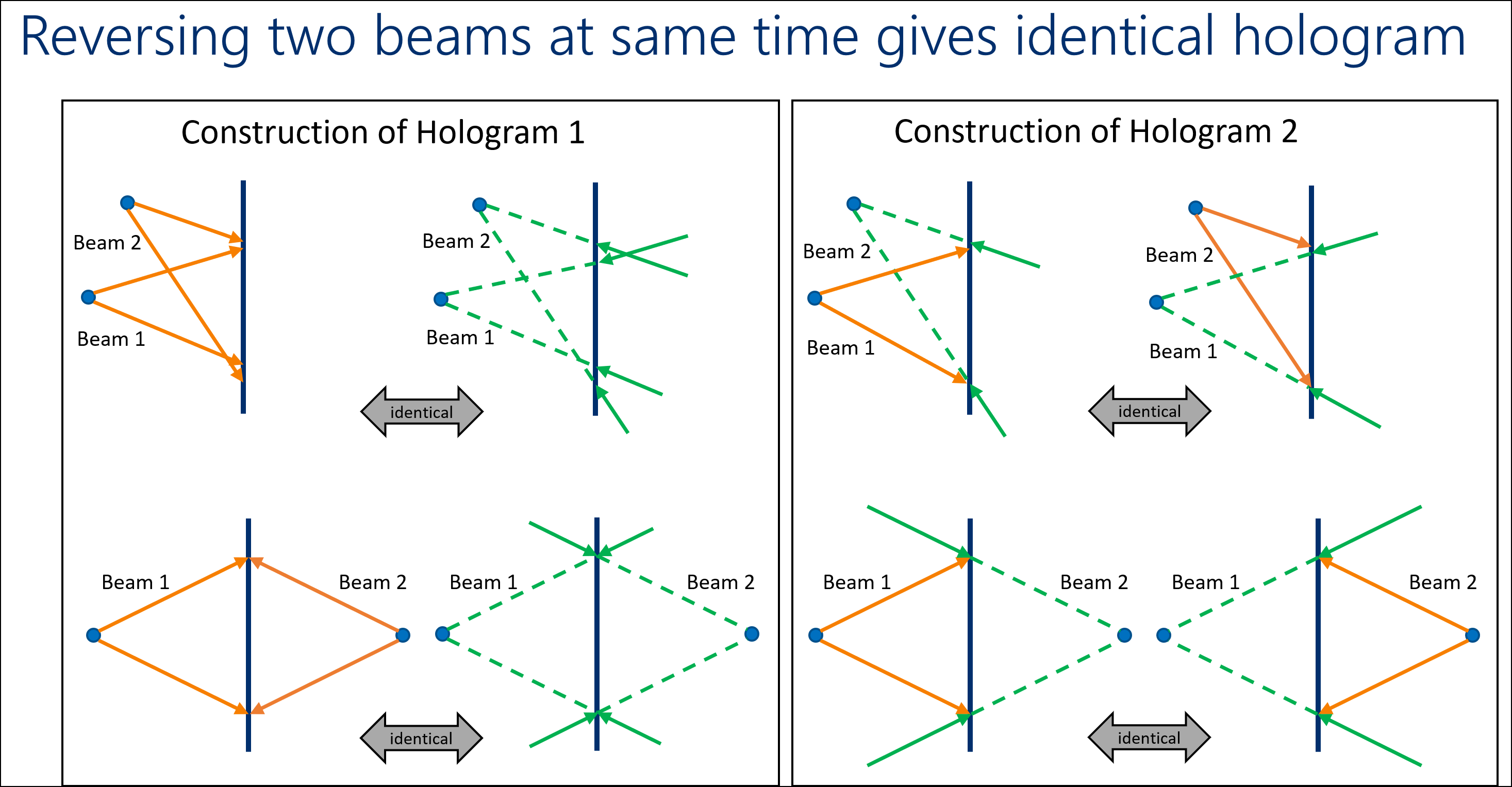
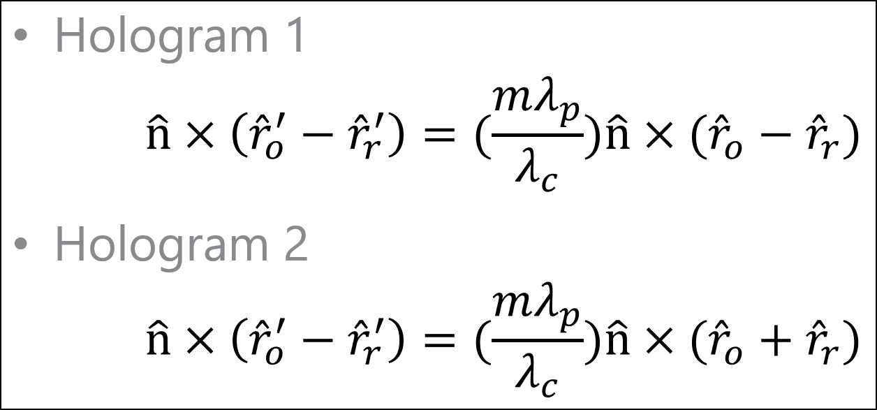
It should be 2 only when the STOP surface in one of the construction systems is in MIRROR space and the STOP in the other construction system is not in MIRROR space. By 'in MIRROR space', I mean the STOP is at after an odd number of MIRROR surfaces in the system.

Ā 

The parameter 'Diffract Order'

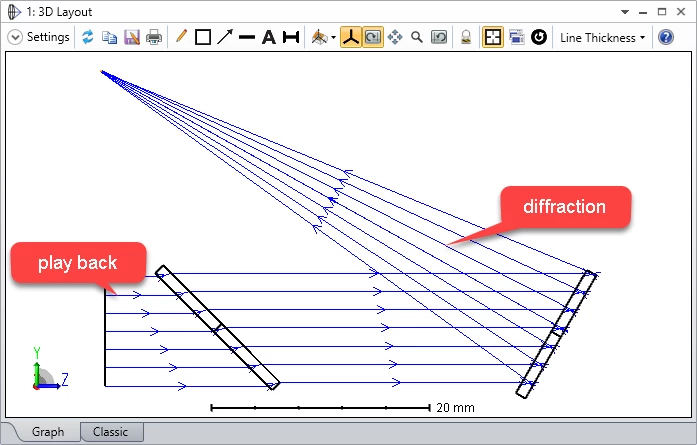
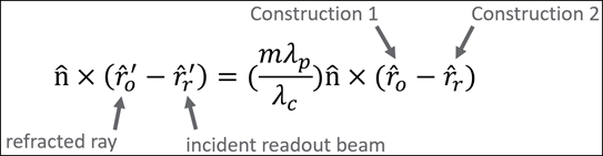
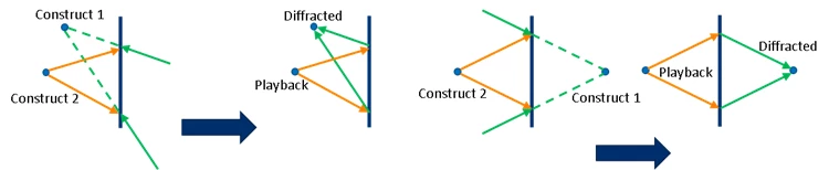
The rule described here actually works to all hologram models in OpticStudio. This parameter will always be either +1 or -1. It needs to be tested to see which is correct. The principleĀ is, if the play back beam mimics the construction beam 1 or 2, it should be diffracted like the other construction beam, 2 or 1 correspondingly. We can use this principle to check if the Diffract order is correctly set.

Ā 

Ā 

200605-231038-image.png

Ā 

How to set up a reflection hologram.

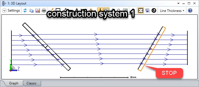
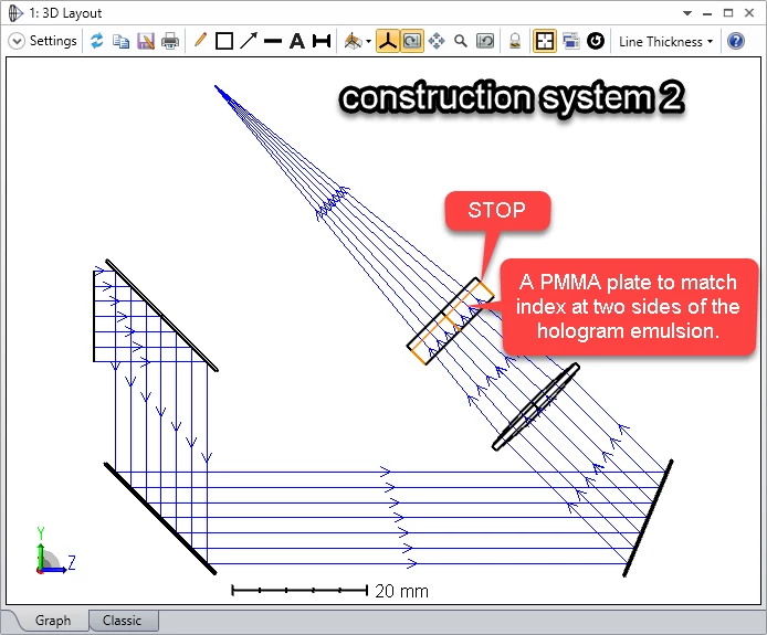
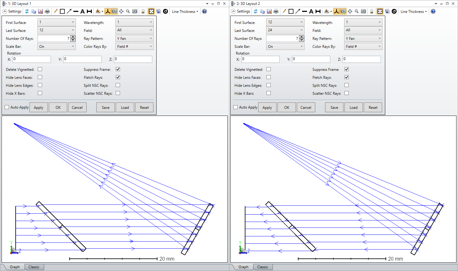
Attached in this post, we have included an set-up example for a reflection hologram as shown in following pictures.

While looking at the example, there are some points that areĀ worth noticing:

  1. In the construction system 2, the beam hits the STOP (hologram) in MIRROR space, so in the playback system, the OFH is set with Holo type = 2.
  2. The STOP (hologram) surface in the construction systemĀ is surrounded by same material as itself. This can eliminate any consing problems.
  3. A PMMA plate is added in front of the STOP surface (hologram) in construction system 2. This is used to match the index. Note it's not an ad-hoc in simulation. It's real thing designer would add in the real world. More explanation can be found inĀ Simulating diffraction efficiency of a volume holographic grating using Kogelnikā€™s method

200605-235635-image.png

Ā 

200605-235642-image.png

Ā 

Ā 

200605-235618-image.png

Ā 

Ā 


8 replies

Userlevel 7
Badge +3

This is a really good post Michael, thank you. The Optically Fabricated Hologram is very powerful, and modeling three optical systems in one system is tricky, so it's good to see some how-to information on it. 


One trick for checking your setup is useful. OS has a Retro-Reflect surface, in the Idealized surface category:


This acts like a phase-conjugate mirror, and so produces a time-reversed wavefront. If you use it after going through the OFH, you should reconstruct the input beam perfectly. It's a great way to check that everything is working exactly as you expect.


Userlevel 6
Badge +2

That is a great trick! I didn't realized the Retro Reflect can be a phase-conjugate element and can be even used to test the OFH!


Thank you for sharing, Mark!

Userlevel 7
Badge +3

Let me add another trick šŸ˜


Use the Make Double Pass tool to make a double pass of your playback system. Then go to the mirror surface that OS creates and change its surface type to Retro-Reflect. The playback beam should exactly recreate the readout beam is all the settings are correct.

Userlevel 6
Badge +2

I have made an example based on this post so users can check.:D


I read the 'Simulating diffraction efficiency of a volume holographic grating using Kogelnikā€™s method' article and went through the sample files.Ā  I cannot find the sample zpl macro as shown in Figure 11.Ā  How do I access it?Ā  What is it called?

Userlevel 6
Badge +2

Hi Deanna,


I have uploaded it to the KBA. Just in case, I have attached the ZPL in this reply too.


Please let me know if you have any more questiosns.


Thank you.


Best regards,


Michael

Userlevel 6
Badge +2

Letā€™s understand the sign convention for the hologram model by looking at the equation!

So, in OpticStudio, we use the following equation to calculate the ray-tracing. For any point on the holographic surface, we always have 4 vectors, two forĀ  construction rays (ro, rr),Ā one for incident ray (rr'), and one for diffracted ray (ro').

Ā 

There are a lot of sign convention we can learn from this equation. Understanding this will help to clarify many common question about signs of diffraction order difference between Holo Type 1 and 2, and so on.

So, here is a list:

  1. If you setĀ Holo type = 1. It works exactly same as this equation. However, if Holo type = 2, the construction 1 changes its sign, so it's "-ro-rr" in the parentheses at right side.
  2. If in OFH, your construction system is virtual propagation on the STOP, the sign of the construction rays (ro or rr) change too. This is because the power actually flowĀ in opposite direction. You should be very careful is you have virtual propagation in construction system for OFH. We actually suggest you always avoid virtual propagations on STOP surface in construction systems for OFH.
  3. If the STOP in the construction system is in MIRROR space, in other words, after odd mirrors, the beam should be considered as virtual propagation. This is a special rule only for OFH. For Hologram 1/2, we don't need to worry about this.
  4. If both construction beams 1 and 2 reverse their propagation direction, which means you change the sign for rr and ro, you get same hologram by also changing the sign of the diffraction order m. This is physically true. This is why we only needs Holo type 1 and 2. If you change two diverging source into two converging source, you construct the same hologram. And, if you a system with ā€œbeam 1 diverge + beam 2 convergeā€ to ā€œbeam 1 converge + beam 2 divergeā€, you get the same hologram.

Ā 

Ā 

Ā 

Ā 

Reply