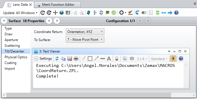
Can the 'To Surface' not default to surface 0 (the object surface)? It almost always generates an error. Would an 'Auto Apply' check box work here?
+1 on the Coordinate Break wizard!
Agreed. This would be extremely valuable when simulating perturbations in systems, especially off-axis systems.
Excellent talk. +1 on the wizard.
Can the 'To Surface' under Coordinate Return not default to surface 0 (the object surface)? That almost always generates an error. Would an 'Auto Apply' check box work here?
Hi all!
First off, thanks for attending the Coordinate Break workshop! I've attached the slides from the presentation here as a PDF, as well as the files I was working with. Please let me know if anyone has any questions on them!
I also wanted to address some of the points on thread here so far, as well as a question or two from the session itself.
First off, thanks everyone for the feedback on an enhancement to the Coordinate Break wizard. I'll happy pass this on internally for further review!
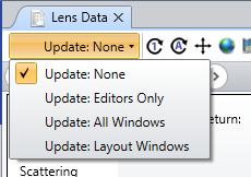
Second, regarding the Coordinate Return 'To Surface' setting, I believe the reason it currently defaults to Surface 0 is that the 'To Surface' always needs to be initialized at a surface that is currently defined in the Lens Data Editor and also be at a surface prior to the one being modified. Since even Surface 1 can be edited to be a Coordinate Break, with a Coordinate Return defined, the only target surface that could exist for Surface 1 would be the Object surface. What could be causing issues, then, is an incompatibility with the position of Surface 0 if you select something like 'Orientation, XYZ' and the Object is at infinity. The Auto Apply checkbox is really a setting that will not push changes to analysis windows as you modify the settings, but you could change your Update Mode to 'None' to prevent any kind of system updating/recomputing until you've made all the edits you want:
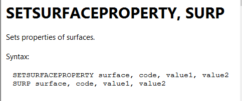
Third, I know there was a question about typing in the desired target surface for a Coordinate Return setting, and while there is no direct way to do this in the GUI, you could work around this by writing a short ZPL macro. In the ZPL, the keyword to modify surface properties is SETSURFACEPROPERTY, or SURP (from our Help Files at 'The Programming Tab > About the ZPL > KEYWORDS (about the zpl) > SETSURFACEPROPERTY, SURP'):
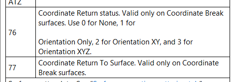
The input are as follows: surface will define the surface whose property you'd like to modify, code will define the specific property to change, and value1/value2 will define the new value/values (which depends on the code being used). Modifying the Coordinate Return settings are codes 76 and 77:
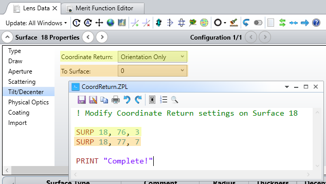
So, the ZPL code might look something as follows to re-define the Coordinate Return settings:
Then, running the macro will push the changes to Surface 18:
If you're relatively new to ZPL macros, you can check out our learning path here that covers some background and examples for writing different kinds of ZPL code.
Lastly, we had a question of someone curious how this could be applied to a system with a prism. Like the fold mirror, this kind of system has Coordinate Breaks inherent to the setup, so while some details are a bit different, the overall approach is essentially the same. This is also covered in another forum post here (you will have to scroll down a couple of posts to see it!).
Thanks again, everyone! Please feel free to continue the discussion here with additional comments, questions, feedback, all that jazz :)
~ Angel