Off-axis conic mirrors in Zemax can be created by adding an off-axis aperture to a rotationally symmetric mirror. It is sometimes inconvenient to have the origin of the off-axis mirror at the vertex of the parent mirror, though, for tasks like positioning and pivoting during tolerancing. Also, larger mirrors are polished directly into blanks, so the substrate edges are roughly parallel to the surface normal at the vertex. The Off-Axis Conic Freeform can be used to represent these off-axis mirrors, instead, so that the local origin is located at the vertex of the part and the substrate shape is correct.

Off-axis mirrors can be converted from Standard surface types to Off-Axis Conic Freeforms using a few key values from the surface.
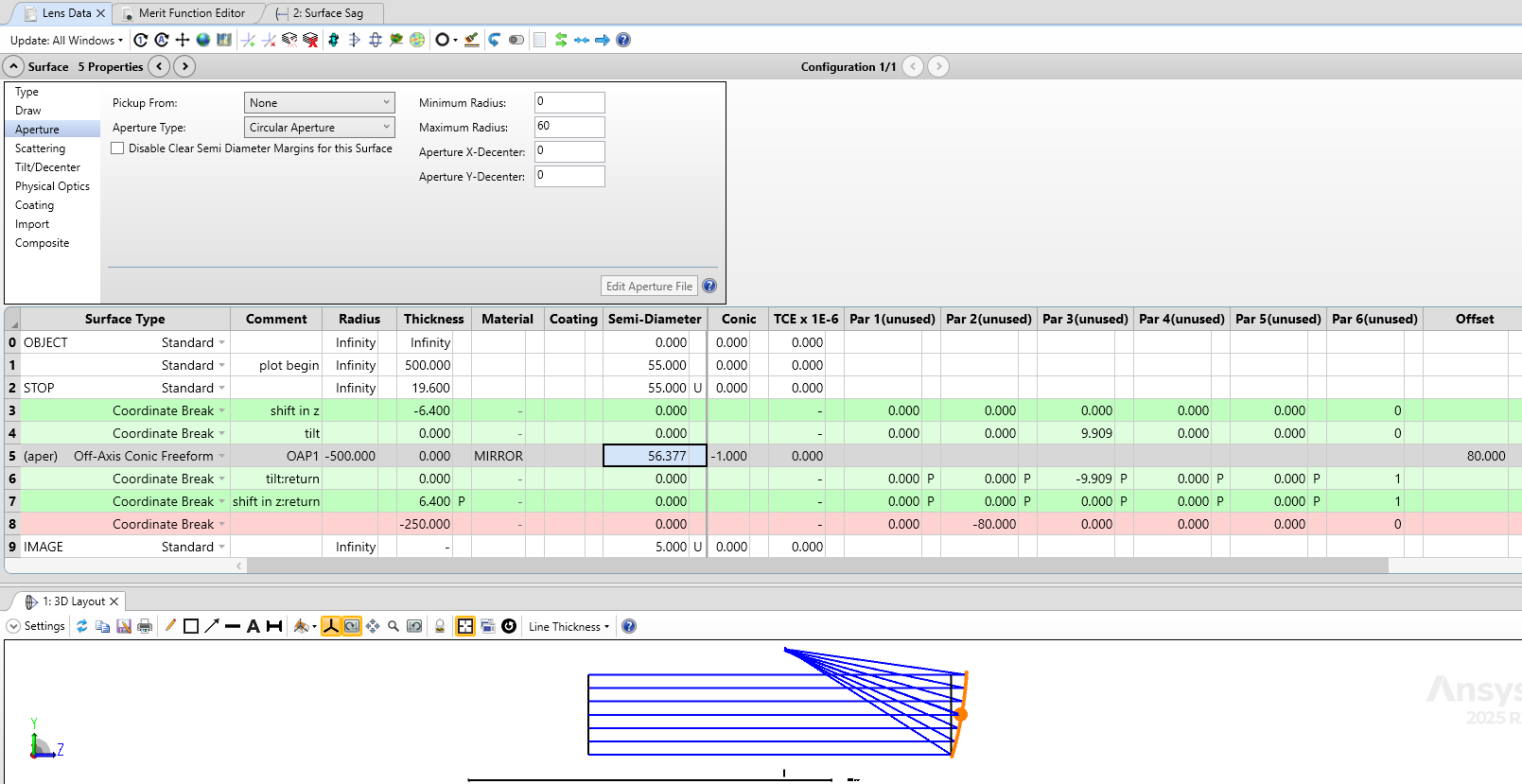
In the Lens Data Editor for the starting system, we’ve got a standard off-axis parabola at surface 4. We’ll replace this with the Off-Axis Conic Freeform. The aperture is decentered by 80 mm, and a Coordinate Break is used to shift the mirror down by 80 mm after the stop surface.

In this example, the system has symmetry about the YZ plane and the aperture is offset along the Y-axis only. As sketched below, the new off-axis mirror will be positioned at dY (the distance of the off-axis aperture on the starting surface) and dZ (the sag of the surface at the center of the off-axis aperture). The Off-Axis Conic surface will also need to be tilted by the tilt of the starting surface at the center of the off-axis vertex.

We can retrieve the values that needed using SSAG and SSLP operands in the Merit Function Editor, as shown below.

To check for mistakes, we also set up operands that check the global vertex location of the surfaces after the OAP (6, 8, and 11). And check the global ray coordinates on each surface (4, 6, 8, and 11). These values must remain unchanged in the final system, so we’ve copied the ”Value” column into the “Target” column for each operand.

Now, I make the following changes in the Lens Data Editor:
- - Remove all pickups and solves!
- - Move the Coordinate Break to immediately after the OAP on line 4.
- - Remove the decenter from the aperture on the OAP.
- - Change the surface type to Off-Axis Conic Freeform. Give it an Offset value of 80 mm.
- - Use the Tilt/Dec tool to add two pairs of coordinate breaks around the OAP. The inner pair will hold the Tilt about X, and the outer pair will hold the shift in Z.
- - Copy the dZ value from row 3 of the Merit Function in the starting file, and place in the Thickness cell of row 3 in the LDE of the new file.
- - Copy the Tilt about X value from row 7 of the Merit Function, and paste it into the Tilt about X column of row 4 in the LDE of the new file.

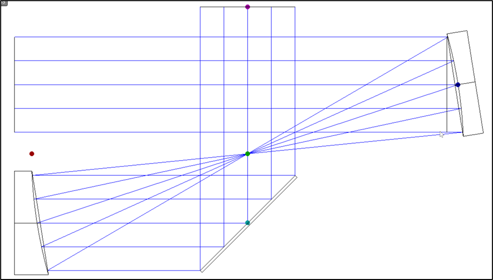
And the final system is identical to the starting system, except for the origin point and substrate appearance of the OAP.