Hi everyone,
I was trying to solve the following problem, and stumbled across an odd behaviour of a ZPL Solve.
Imagine a collimated beam incident upon a Fold Mirror. The Reflect Angle is arbitrary. I want the next surface to retain its orientation irrespective of the Fold Mirror orientation. For example, if the Reflect Angle is -80 deg, and I want the next surface to have an overall tilt about X of -90 deg, I would add a Coordinate Break after the Fold Mirror and put a value of -10 deg in the Tilt About X column. This works. Now to deal with arbitrary angles, my idea was to have a ZPL Solve that would take the Tilt About X of the second Coordinate Break of the Fold Mirror, double it, add 90 deg, and change its sign. This works in the sense that the value returned for the -80 deg Fold Mirror is indeed -10 deg, but the 3D Layout looks very different and I can’t wrap my head around it.
This is the ZPL Solve:
fold_return = SOSO(0) - 1
fold_tilt = -2 * parm(3, fold_return) - 90
SOLVERETURN fold_tilt
These are screenshots of the situation and I’ll attach my file at the bottom of this post:


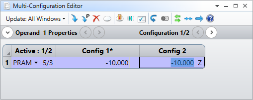
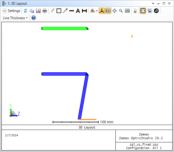
I’ve highlited the IMAGE Surface in orange and shown two configurations of the Tilt About X of Surface 5 (with a Y Offset for visualization). In the Multi-Configuration Editor, the value is exactly the same, but in the 3D Layout, Configuration 1 (Blue rays) has the large horizontal surface at the bottom, which is what I expect and Configuration 2 (Green rays) has the small angled surface on the right-hand side.
Thanks for your help and take care,
David


