I use the same bmp as input and but got different shape of a the edge (square vs. circular), what could be the reason?

I use the same bmp as input and but got different shape of a the edge (square vs. circular), what could be the reason?
Best answer by David.Nguyen
In your PSF Grid, you can see that the top rows are becoming increasingly square. The Image Simulation is a result of the convolution of the PSF at the corresponding grid location in the image. If the PSF is a square and you convolve a circle in your image with a square, the resulting shape will start to look square as well (particularly is if the square is larger than the circle). The reason the PSF becomes square is because it is getting large and Image Simulation considers only a sub-region around the grid location for a given PSF. This is specified in the Image Sampling setting. You can try to increase this setting to better capture the actual PSF grid, but it comes at the cost of computation time. I couldn’t reproduce your results with the blackbox file, but I can illustrate my point in a simple example.
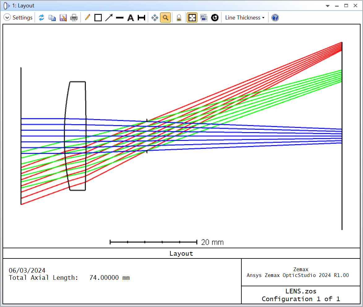
Take this extremely out-of-focus dummy lens:
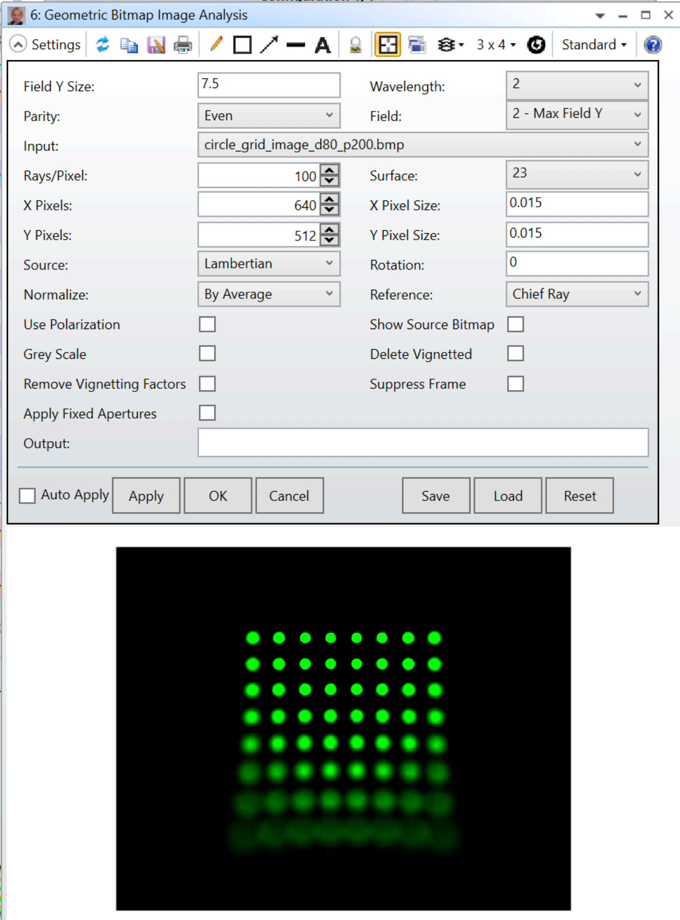
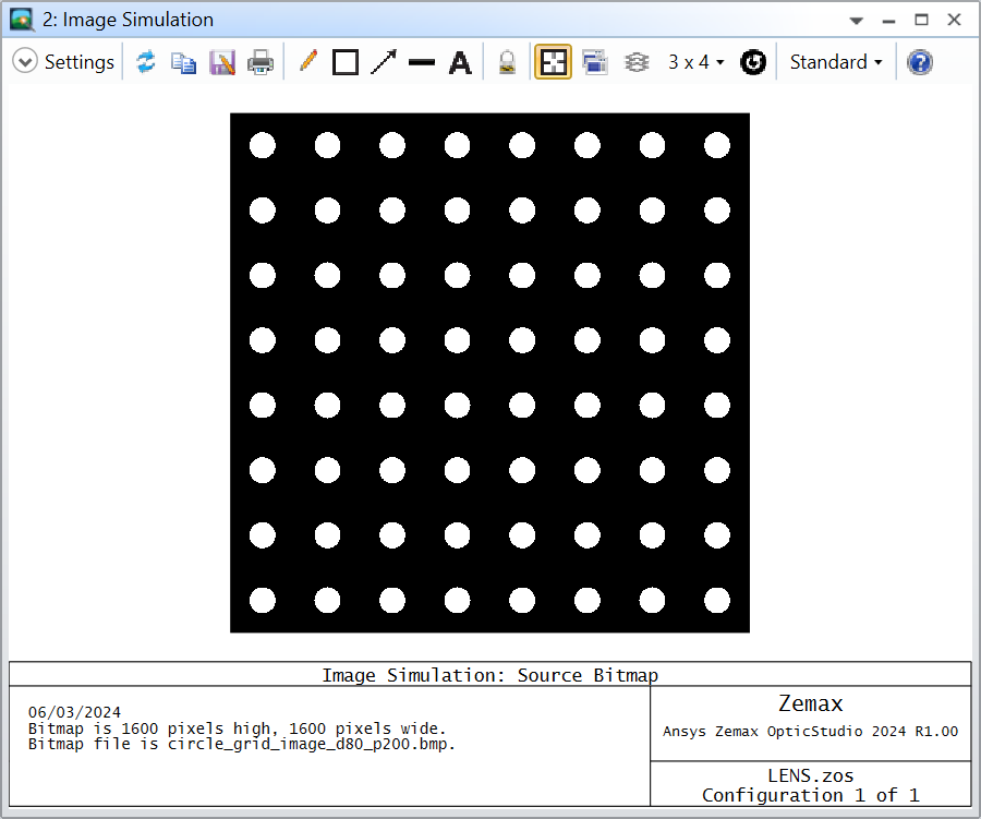
And we will use your original image:
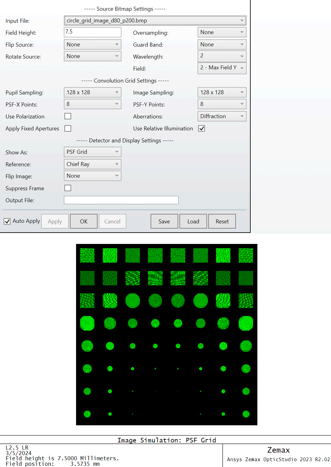
For simplicity, I will only use a single PSF in the center. The single PSF with an Image Sampling of 128 x 128 looks like so:
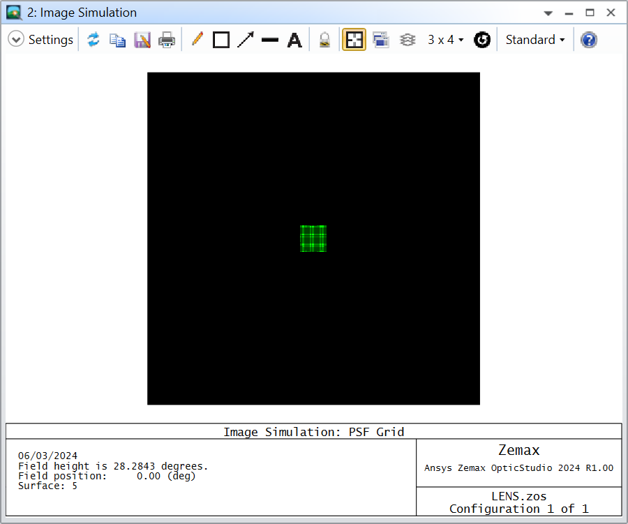
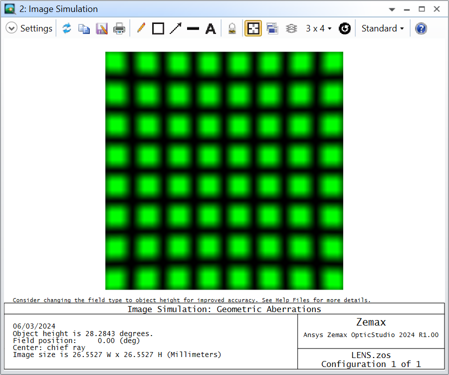
Very much like a square. This is because the real underlying PSF is much larger than 128 x 128 pixels in the image space. Therefore, the circles from your source image are convolved with this square PSF and they tend to become squares:
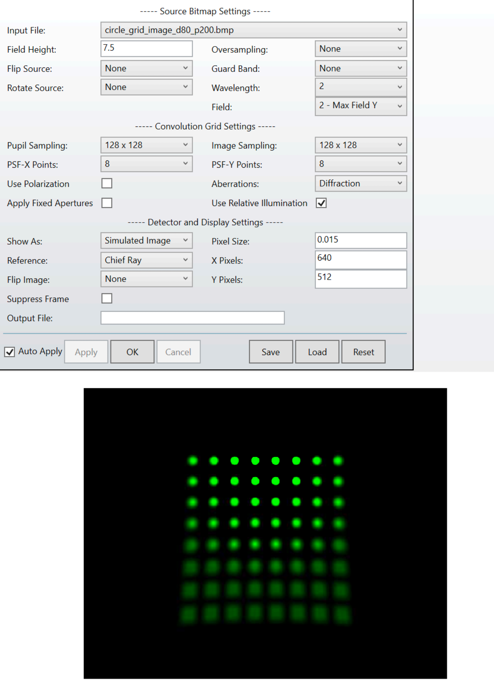
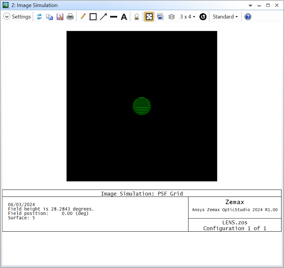
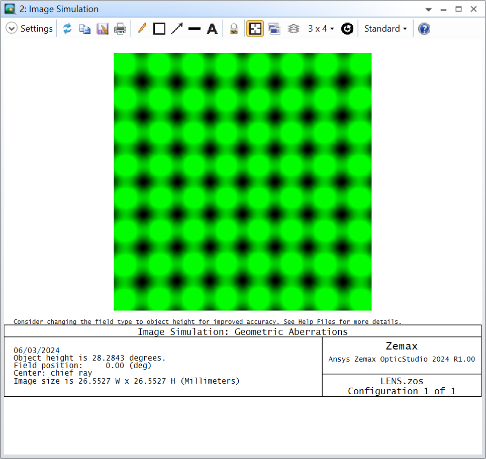
Now I can increase the Image Sampling until I get a PSF that makes sense. You might not know what to expect for your PSF of course, but as a general tip: If you increase the Image Sampling setting and the PSF grid changes significantly, then you are not using a large enough Image Sampling. In my case changing to 256 x 256 gets me a round PSF and it doesn’t change much if I go to 512 x 512, so I’ll keep 256 x 256:
And the resulting image simulation still has the circles in it, they are only “blurred” by the circular PSF (and they even start touching one another but I hope you get my point):
Let me know if that helps solving your problem and take care,
David
Enter your E-mail address. We'll send you an e-mail with instructions to reset your password.
Do not provide any information or data that is restricted by applicable law, including by the People’s Republic of China’s Cybersecurity and Data Security Laws ( e.g., Important Data, National Core Data, etc.).
不要提供任何受适用法律,包括中华人民共和国的网络安全和数据安全法限制的信息或数据(如重要数据、国家核心数据等)。