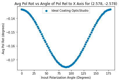
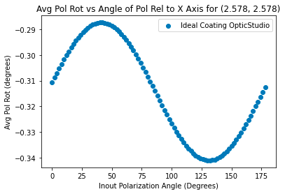
I am looking at a pair of polynomial mirrors for a Crossed-Dragone telescope design. I am interested in finding the instrument polarization of these mirrors. To do that, I have been experimenting with how the input polarization for a given field, wavelength, and surface affects the polarization pupil map. Using the ZOS-API, I have written a script that varies the input polarization from 0 to 180 degrees with respect to the X axis, calculates the pupil map with the wavelength, field, and surface fixed, averages over the pupil map, and then graphs the polarization rotation due to the mirrors vs the input polarization. I am finding that there is a sinusoidal oscillation in this relationship which I have been having some difficulty rationalizing.
I have the I.0 coating applied to both mirrors and I am consistently getting 100% transmission in my pupil maps, so I do not think that this sinusoidal oscillation is the result of a differential reflection in X or Y polarization. My hypothesis is that the sinusoidal oscillation is a result of an aberration in phase that primarily affects either the X or Y polarization for a given field, which is causing there to be a difference in the polarization state measured at the image surface depending on if the input field is primarily X or Y polarized. I have attached two graphs at the bottom of the email documenting what I am seeing. Both graphs were taken with a wavelength of 300 um.
Does this explanation seem sensible? If not, is there an alternative explanation that could explain this oscillation? Thank you.